Leonton REG5-2602-2C Series Скачать руководство пользователя страница 15

11 


Wiring the Fault Alarm Contact 

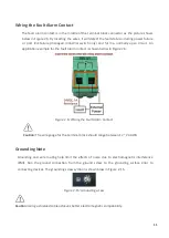
The fault alarm contact is in the middle of the terminal block connector as the picture shows 

below in Figure 2.6. By inserting the wires, it will detect the fault status including power failure 

or  port  link  failure  (managed  industrial  switch  only)  and  form  a  normally  open  circuit.  An 

application example for the fault alarm contact is shown below in Figure 2.6. 


Figure 2.6: Wiring the Fault Alarm Contact 


Caution:

 The wire gauge for the terminal block should range between 12 ~ 24 AWG. 


Grounding Note 

Grounding  and  wire  routing  help  limit  the  effects  of  noise  due  to  electromagnetic  interference 

(EMI).  Run  the  ground  connection  from  the  ground  screw  to  the  grounding  surface  prior  to 

connecting devices. The grounding screw symbol is shown blow in Figure 2.15. 


Figure 2.15: Grounding screw 


Caution:

 Using a shielded cable achieves better electromagnetic compatibility. 


Содержание REG5-2602-2C Series

Страница 1: ...LEONTON REG5 2602 2C Series REG5 2602 2C REG5 2602 2C T User Manual...

Страница 2: ...t not limited to the implied warranties of merchantability and fitness for a particular purpose LEONTON Technologies Co Ltd may make improvements and or changes to the product and or specifications of...

Страница 3: ...the equipment off and on the user is encouraged to try to correct the interference by one or more of the following measures Reorient or relocate the receiving antenna Increase the separation between t...

Страница 4: ...ption 4 Physical Dimensions 4 Front Panel 5 Rear Panel 5 LED Indicators 5 Ethernet Ports 7 Cabling 8 Wiring the Power Input 10 Wiring the Fault Alarm Contact 11 Grounding Note 11 Mounting Installation...

Страница 5: ...ndustrial automation outdoor application and harsh environments Software Features Software Features Layer 3 Switching Static Routes Management CLI Http Https SNMP SSH Telnet Security Access Management...

Страница 6: ...ure model T 40 C 75 C Case Installation IP 40 protection Installation in a Pollution Degree 2 industrial environment Rack mount design Package Contents 1 REG5 2602 2C T 2 Rack mounting brackets and sc...

Страница 7: ...3 Figure 1 2 Hot Surface Warning Label...

Страница 8: ...4 Hardware Description Physical Dimensions Figure 2 1 below shows the physical dimensions of REG5 2602 2C series W x D x H is 440mm x 200mm x 44mm Figure 2 1 REG5 2602 2C Series Physical Dimensions...

Страница 9: ...REG5 2602 2C series switch that is equipped with one AC power inputs socket 90 264VAC and one 2 pin terminal block for relay output Figure 2 3 The Back Panel of REG2 2602 2C Series LED Indicators The...

Страница 10: ...onnected to network 1000Mbps Flashing Networking is active Off Not connected to network 10 100 LAN Port 1 24 Green On Connected to network 10 100Mbps Flashing Networking is active Off Not connected to...

Страница 11: ...onnections Auto MDI MDIX means that the switch can connect to another switch or workstation without changing the straight through or crossover cabling See the figures as below for straight through and...

Страница 12: ...45 port connections The cable between the switch and the link partner switch hub workstation etc must be less than 100 meters 328 ft long The small form factor pluggable SFP is a compact optical tran...

Страница 13: ...C connector into the transceiver as shown below in Figure 2 9 Figure 2 9 LC Connector to the Transceiver To remove the LC connector from the transceiver please follow the steps shown below Step 1 Pres...

Страница 14: ...as shown below in Figure 2 4 Figure 2 4 Pull Out from the SFP Module Wiring the Power Input Caution Please follow the below steps to insert the power wire Step 1 Insert the AC power cable into the uni...

Страница 15: ...fault alarm contact is shown below in Figure 2 6 Figure 2 6 Wiring the Fault Alarm Contact Caution The wire gauge for the terminal block should range between 12 24 AWG Grounding Note Grounding and wir...

Страница 16: ...mounting switch Locate one plate to align with the holes on one side of the switch and secure it with the plate screws and then attach the remaining plate to the other side of the switch Please refer...

Страница 17: ...llation Step 3 Power on the industrial Ethernet switch and then the power LED light will turn on If you need help on how to wire power please refer to the Wiring the Power Inputs section Please refer...

Страница 18: ...l as other cables Be careful when handling them so as to not trip over Do not under any circumstance insert foreign objects of any kind into the heat dissipation holes located in the different faces o...

Страница 19: ...ssist in identifying problems the switch can be easily monitored with the LED indicators which help to identity if any problems exist Please refer to the LED Indicators section for LED light indicatio...

Отзывы: