LEONTON
GINJ-0201-AT-24 Series
(GINJ-0201-AT-24 / GINJ-0201-AT-24-T)
User Manual
Страница 1: ...LEONTON GINJ 0201 AT 24 Series GINJ 0201 AT 24 GINJ 0201 AT 24 T User Manual...
Страница 2: ...t not limited to the implied warranties of merchantability and fitness for a particular purpose LEONTON Technologies Co Ltd may make improvements and or changes to the product and or specifications of...
Страница 3: ...the equipment off and on the user is encouraged to try to correct the interference by one or more of the following measures Reorient or relocate the receiving antenna Increase the separation between t...
Страница 4: ...tion 1 Physical Dimensions 1 Front Panel 2 Top View 2 LED Indicators 3 Cabling 3 Wiring the Power Inputs 3 Grounding Note 4 Mounting Installation 5 DIN Rail Mounting 5 Wall Mounting 7 Hardware Install...
Страница 5: ...utput for better usage in the automation industry GINJ 0201 AT 24 Series with fan less design besides extending surely apply to various industrial application GINJ 0201 AT 24 Series works perfectly in...
Страница 6: ...30 protection Installation in a Pollution Degree 2 industrial environment DIN Rail and wall mount design Package Contents 1 GINJ 0201 AT 24 T product 2 Wall mounting brackets and screws 1 Quick Insta...
Страница 7: ...Hardware Description Physical Dimensions Figure 2 1 below shows the physical dimensions of GINJ 0201 AT 24 series W x D x H is 26mm x 75mm x 95mm Figure 2 1 GINJ 0201 AT 24 Series Physical Dimensions...
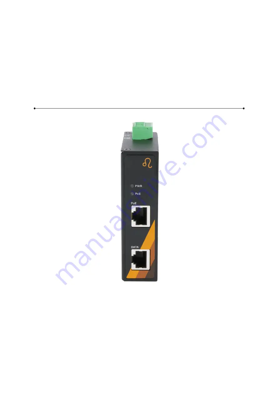
Страница 8: ...low in Figure 2 2 Figure 2 2 The Front Panel of GINJ 0201 AT 24 Series Top View Figure 2 3 below shows the top panel of the GINJ 0201 AT 24 series injector that is equipped with one 4 pin removal term...
Страница 9: ...No powered device attached or power supplying fails Table 2 4 LED Indictors for GINJ 0201 AT 24 Series Caution PWR is the abbreviation for Power Cabling Use the four twisted pair category 5e or the ab...
Страница 10: ...terminal block should range between 18 20 AWG Grounding Note Grounding and wire routing help limit the effects of noise due to electromagnetic interference EMI Run the ground connection from the grou...
Страница 11: ...and DIN Rail Bracket Follow the steps below to learn how to hang the industrial PoE Injector Step 1 Use the screws to install the DIN Rail bracket on the rear side of the industrial PoE Injector Cauti...
Страница 12: ...pull down the bracket on to the rail as shown below in Figure 3 3 Figure 3 3 Stable the Injector on DIN Rail Step 5 Check if the bracket is mounted tightly on the rail Step 6 To remove the industrial...
Страница 13: ...by loosening the screws Step 2 Place the wall mounting brackets on the top and bottom of the industrial PoE Injector Step 3 Use the screws to screw the wall mounting bracket on the industrial PoE Inj...
Страница 14: ...8 Below in Figure 3 5 are the dimensions of the wall mounting bracket Figure 3 5 Wall Mounting Bracket Dimensions...
Страница 15: ...d on the industrial PoE Injector please refer to the DIN Rail Mounting section for DIN Rail installation If you want to wall mount the industrial PoE Injector please refer to the Wall Mounting section...
Страница 16: ...l as other cables Be careful when handling them so as to not trip over Do not under any circumstance insert foreign objects of any kind into the heat dissipation holes located in the different faces o...
Страница 17: ...meters 328 feet NOTE The total length from the device A through the Injector to the device B must not exceed 100 meters Diagnosing LED Indicators To assist in identifying problems the injector can be...