


15
Hardware Installation
Installation Steps
This section will explain how to install EG2-2004-SFP series.
Installation Steps
Step 1.
Unpack the industrial Ethernet switch from the original packing box.
Step 2.
Check if the DIN-Rail bracket is screwed on the industrial Ethernet switch.
•
If the DIN-Rail is not screwed on the industrial Ethernet switch, please refer to the
DIN-Rail
Mounting
section for DIN-Rail installation.
•
If you want to wall mount the industrial Ethernet switch, please refer to the
Wall Mounting
section for wall mounting installation.
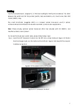
Step 3.
To hang the industrial Ethernet switch on a DIN-Rail or wall, please refer to the
Mounting
Installation
section.
Step 4.
Power on the industrial Ethernet switch and then the power LED light will turn on.
•
If you need help on how to wire power, please refer to the
Wiring the Power Inputs
section.
•
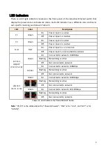
Please refer to the
LED Indicators
section for LED light indication.
Step 5.
Prepare the twisted-pair, straight-through category 5 cable for Ethernet connection.
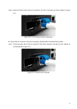
Step 6.
Insert one side of the RJ-45 cable into switch’s Ethernet port and on the other side into
the networking device’s Ethernet port, e.g. switch PC or server. The Ethernet port’s (RJ-45)
LED on the industrial Ethernet switch will turn on when the cable is connected to the
networking device.
•
Please refer to the
LED Indicators
section for LED light indication.
Step 7.
When all connections are set and the LED lights all show normal, the installation is
complete.


