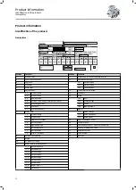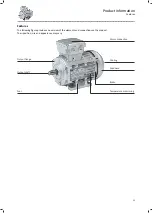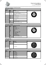
Power connection
Bridge arrangement
Y/Δ circuit
W2
U2
V2
U1
V1
W1
L1
L2
L3
W2
U1
U2
V1
V2
W1
L1
L2
L3
Contact
Name
Meaning
PE
PE
PE conductor
U1
L1
Motor winding phase
V1
L2
W1
L3
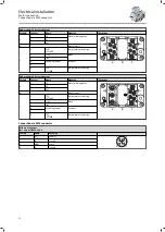
DC brake connection
Contact
Name
Meaning
BD1
+
Brake +
BD2
-
Brake -
Connection of brake AC
Connection via rectifiers
Contact
Name
Meaning
~
L1
Mains
1 2 3 4 5 6
-
~
~ +
~
N
+
+
Holding brake
(factory-wired)
-
-
Switching contact - DC switching
Feedback connection
Resolver
Contact
Name
Meaning
B1
+Ref
Transformer windings (reference windings)
B2
-Ref
B3
+VCC ETS
Power supply: electronic nameplate
(Only for model with electronic nameplate ETS)
B4
+COS
Cosine stator winding
B5
-COS
B6
+SIN
Sine stator winding
B7
-SIN
B8
Not assigned
Incremental encoder HTL/TTL
Contact
Name
Meaning
+
+ UB
-
GND
Mass
A
A/+COS
Track A / + COS
A¯
A¯/Ref COS
Track A inverse / - COS
B
B/+SIN
Track B / + SIN
B¯
B¯/Ref SIN
Track B inverse/-SIN
0
0
Zero track / + RS485
0¯
0¯
Zero track inverse / - RS485
Electrical installation
Motor connection
Connection via terminal box
26

