Mechanical installation
Mounting of g500 short/servo adapters with clamping connection
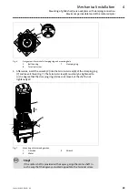
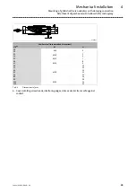
Maximum permissible load at the motor adapter
26
Lenze ¯ MA 12.0018 ¯ 4.1
Drive size
Distance L
Tab
of
the motor
Gearbox type
IEC
NEMA
g500−S8000
G50BS280
g500−S14000
G50BS314
g500−S19000
G50BS319
[mm]
Maximum permissible force F
M Tab
[N]
T
H
51
A
B
14
115
−−−−−
−−−−−
−−−−−
55
18
145
2210
−−−−−
−−−−−
55
−
145
2490
2450
2450
61
21
190
4480
4420
4420
65
25
250
5230
5230
5230
66
28
250
4500
4500
4500
70
−
300
3720
3720
3720
76
32
300
7100
7100
7100
81
36
400
6880
6880
6880
82
−
400
11400
11400
11400
4.3.6
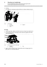
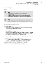
Mounting of g500 short/servo adapters with clamping connection
Important notes
¯
The transmission is made in a force−fitting manner via a clamping connection.
Greases, oils and other substances which reduce the friction factor reduce the
torque to be transmitted which is why these should be avoided in the connection.
¯
The motor shaft diameter must be designed with fit k6.
¯
The motor centering diameter must be designed with fit j6.
¯
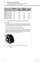
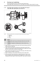
With regard to smooth running tolerance of the motor shaft, concentricity of the
centering and axial runout of the mounting flange, the motor must fulfil the
requirements according to DIN 42955 R (reference values for smooth running <
0.025 mm; axial runout and concentricity < 0.05 mm).
4
5
Fig. 3
Measurement of the surfaces of smooth running, axial runout and concentricity
4
Motor flange
5
Centering


