background image

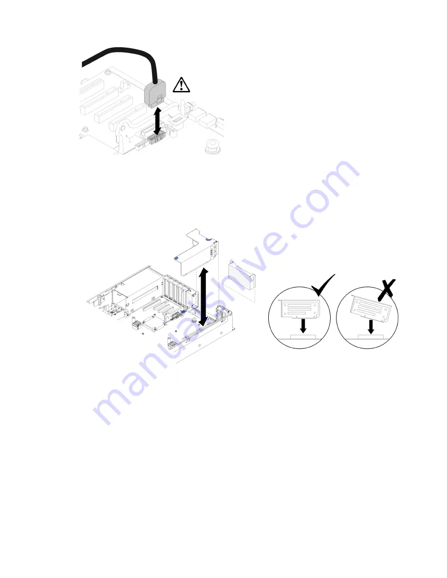
Figure 82. Removing USB 3.0 connector vertically

To remove the PCIe riser-card assembly, complete the following steps:

Step 1.  Disconnect any cables connected to the adapter(s).

Step 2.  Grasp the PCIe riser-card assembly at the touch-points, and lift it out from the system board. 

Figure 83. PCIe riser-card assembly removal 

Step 3.  Remove the screws that fix the PCIe riser-card, and slightly push it away to detach it from the riser- 

cage. 

Chapter 3

.

Hardware replacement procedures

87

Содержание ThinkSystem SR850

Страница 1: ...ThinkSystem SR850 Maintenance Manual Machine Type 7X18 and 7X19 ...

Страница 2: ...addition be sure that you are familiar with the terms and conditions of the Lenovo warranty for your server which can be found at http datacentersupport lenovo com warrantylookup Second Edition August 2017 Copyright Lenovo 2017 LIMITED AND RESTRICTED RIGHTS NOTICE If data or software is delivered pursuant to a General Services Administration GSA contract use reproduction or disclosure is subject t...

Страница 3: ...y 61 Install the fan cage assembly 63 Remove a hot swap fan 64 Install a hot swap fan 65 Front VGA assembly replacement 66 Remove the front VGA assembly 66 Install the front VGA assembly 68 LOM adapter replacement 71 Remove the LOM adapter 71 Install the LOM adapter 72 M 2 drive and backplane replacement 74 How to adjust the position of the retainer on the M 2 backplane 74 Remove the M 2 backplane...

Страница 4: ...oblem determination procedures 141 Resolving suspected power problems 141 Resolving suspected Ethernet controller problems 142 Troubleshooting by symptom 143 Drive problems 143 Fan problems 146 Intermittent problems 146 Keyboard mouse or USB device problems 147 Memory problems 148 Monitor and video problems 149 Network problems 151 Observable problems 151 Optional device problems 153 Power on and ...

Страница 5: ...ert eerst de veiligheidsvoorschriften Ennen kuin asennat tämän tuotteen lue turvaohjeet kohdasta Safety Information Avant d installer ce produit lisez les consignes de sécurité Vor der Installation dieses Produkts die Sicherheitshinweise lesen Prima di installare questo prodotto leggere le Informazioni sulla Sicurezza Les sikkerhetsinformasjonen Safety Information før du installerer dette produkte...

Страница 6: ...ned service personnel as defined by the NEC and IEC 60950 1 Second Edition the standard for Safety of Information Technology Equipment Lenovo assumes you are qualified in the servicing of equipment and trained in recognizing hazards in products with hazardous energy levels Make sure all power cords are disconnected from the system when reading the following step in this manual Turn off the server ...

Страница 7: ...line cords Make sure that the insulation is not frayed or worn 3 Check for any obvious non Lenovo alterations Use good judgment as to the safety of any non Lenovo alterations 4 Check inside the server for any obvious unsafe conditions such as metal filings contamination water or other liquid or signs of fire or smoke damage 5 Check for worn frayed or pinched cables 6 Make sure that the power suppl...

Страница 8: ...vi ThinkSystem SR850 Maintenance Manual ...

Страница 9: ...our specific warranty see http datacentersupport lenovo com warrantylookup Specifications The following information is a summary of the features and specifications of the server Depending on the model some features might not be available or some specifications might not apply Table 1 Specifications Type 7X18 and 7X19 Specification Description Dimension 2U server Height 86 5 mm 3 4 inches Width Wit...

Страница 10: ... bays bay 0 3 8 11 Eight 2 5 inch hot swap SATA SAS NVMe drive bays bay 4 7 12 15 Expansion slots Eleven expansion slots Slot 1 PCI Express 3 0 x16 supports PCIe switch card Slot 2 PCI Express 3 0 x8 supports RAID adapters for SATA SAS drives Slot 3 5 PCI Express 3 0 for PCIe riser card with the following slots available depending on the riser card installed x8 x8 x8 PCIe full height riser assembl...

Страница 11: ...nvironment is 1GB 10GbE LOM adapter minimal bandwidth of network environment is 1GB RAID adapter depending on model The following options with support for RAID levels 0 1 and 10 are available for this server ThinkSystem RAID 530 8i PCIe 12 GB Adapter ThinkSystem RAID 730 8i 1 GB Cache PCIe 12 GB Adapter ThinkSystem RAID 930 8i 2 GB Flash PCIe 12 GB Adapter ThinkSystem RAID 930 16i 4 GB Flash PCIe ...

Страница 12: ...o 90 Particulate contamination Attention Airborne particulates and reactive gases acting alone or in combination with other environmental factors such as humidity or temperature might pose a risk to the server For information about the limits for particulates and gases see Particulate contamination on page 164 Note To maintain component reliability system performance might vary at ambient temperat...

Страница 13: ...firmware only UXSPs are also available See the following table to determine the best Lenovo tool to use for installing and setting up the firmware Tool In band update Out of band update On target update Off target update Graphical user interface Command line interface Supports UXSPs Lenovo XClarity Provisioning Manager Limited to core system firmware only Lenovo XClarity Controller Supports core s...

Страница 14: ...available at http sysmgt lenovofiles com help topic com lenovo systems management xcc doc NN1ia_c_ manageserverfirmware html Lenovo XClarity Essentials OneCLI Lenovo XClarity Essentials OneCLI is a collection of command line applications that can be used to manage Lenovo servers Its update application can be used to update firmware and device drivers for your servers The update can be performed wi...

Страница 15: ...r and find the RNDIS Device Click Properties Driver Reinstall driver Point the server to the Windows inf directory where it can find the ibm_rndis_server_os inf file and install the device Step 2 Click Administrative Tools Device Manager Right click Network adapters and select Scan for hardware changes A small pop up confirms that the Ethernet device is found and installed The New Hardware Wizard ...

Страница 16: ...ickly when connected to input power it enters a standby state power status LED flashes once per second The server can be turned on power LED on in any of the following ways You can press the power button The server can restart automatically after a power interruption The server can respond to remote power on requests sent to the Lenovo XClarity Controller For information about powering off the ser...

Страница 17: ... type model and serial number The model number and serial number are on the ID label on the front of the server as shown in the following illustrations You can also add other system information labels to the front of the server in the customer label spaces XClarity Controller network access label In addition the XClarity Controller network access labelis attached to the pull out information tab lo...

Страница 18: ...tional Connect a monitor to this connector Notes When the optional front VGA connector is in use the rear one will be disabled The maximum video resolution is 1920 x 1200 at 60 Hz 2 Drive activity LED green Each hot swap drive comes with an activity LED and when this LED is flashing it indicates that the drive is in use 3 Drive status LED yellow These LEDs are on SAS or SATA hard disk drives and s...

Страница 19: ...rity Controller Shared mode owned by host In this mode connection to the USB port is shared by the server and XClarity Controller while the port is switched to the server 6 USB 2 USB 2 0 or 3 0 depending on the model 7 Power button LED green Press the power button to turn the server on and off manually This LED indicates power status of the server See Front operator panel on page 12 for more detai...

Страница 20: ...cond The server is turned off and is ready to be turned on You can press the power control button to turn on the server Lit The server is turned on 2 Network activity LED green When this LED is lit it indicates that the server is transmitting to or receiving signals from the Ethernet LAN 3 Identification button LED blue Use this blue LED to visually locate the server among other servers This LED i...

Страница 21: ...system name system status temperature power consumption and UEFI POST code is displayed here 3 Select button Press this button to make your selection from the menu options 2 Scroll up button Press this button to scroll up or scroll to the left in the main menu to locate and select the system information that you want displayed 4 Scroll down button Press this button to scroll down or scroll to the ...

Страница 22: ... blinking in turns with 2 The option menu UI flow on the LCD display is illustrated as following Figure 9 Front operator panel option menu UI flow Following is the list of options available on the front operator panel Switch between an option and the subordinate information entries with Select button and switch among options or information entries with Scroll up and Scroll down buttons 14 ThinkSys...

Страница 23: ...roduct data System vital product data provides the following information Machine type and serial number are displayed as following Machine Type XXXXXXXX Serial Num YYYYYY UUID universally unique identifier is displayed as following UUID ZZZZZZZZZZZZZZZZZZZZZZZZZZZZ Whereas XXXXXXXX is the machine type YYYYYY is the serial number ZZZZZZZZZZZZZZZZZZZZZZZZZZZZ is the UUID System firmware level System...

Страница 24: ...s displayed as following IP Subnet IP Y Y Y Y Gateway IP is displayed as following IP Gateway IP Y Y Y Y Whereas NNNN is the machine type XX XX XX XX XX XX is a MAC address Y Y Y Y is an IPv4 or IPv6 address System environmental information System environmental information provides the following information Ambient temperature is displayed as following Ambient Temperature XX C Processor temperatur...

Страница 25: ... presence is displayed as following REQUEST XCC PHY PRES HOLD v FOR 3s Clear CMOS is displayed as following CLEAR CMOS HOLD v FOR 3s Note This action is only available when the system power is off System reboot is displayed as following SYSTEM RESET BUTTOM HOLD v FOR 3s Rear view This section contains information about the LEDs and connectors on the rear of the server The following illustrations s...

Страница 26: ...supports PCIe switch card For more information see System board connectors on page 21 for the location of the slots and PCIe riser card assembly and adapter replacement on page 86 for information about installation and removal 2 PCIe riser card slot 3 5 Install a full height PCIe riser card into this slot Following are the PCIe riser cards supported by this server x8 x8 x8 PCIe full height riser a...

Страница 27: ...9 Power supply units Install power supply units to these bays connect them to power cords Make sure the power cords are connected properly Following are the power supplies supported by this system 750 watt platinum power supply Input power 115V or 230V ac 1100 watt platinum power supply Input power 115V or 230V ac 1600 watt platinum power supply Input power 230V ac 10 System error LED yellow When ...

Страница 28: ...ou use this connector the Lenovo XClarity Controller cannot be accessed directly from the production network A dedicated management network provides additional security by physically separating the management network traffic from the production network You can use the Setup utility to configure the server to use a dedicated systems management network or a shared network 18 NMI button Press this bu...

Страница 29: ...nnector 2 PCIe slot 7 LOM adapter 11 USB 1 USB 2 0 with Lenovo XClarity Controller management 3 PCIe slot 6 M 2 backplane 12 Backplane connector 2 4 PCIe slot 3 5 PCIe riser card 13 Backplane connector 1 5 PCIe slot 2 1 14 Front VGA connector 6 USB 2 USB 3 0 15 Fan connector 1 6 7 TCM module 16 Processor 1 8 Auxiliary power connector 17 DIMM slot 1 6 7 18 19 24 9 Processor 2 Chapter 2 Server compo...

Страница 30: ...tem board SW13 switch block descriptions on page 22 for more details 2 Light path button Press this button to light the LEDs on the system board when the power source has been removed from the server The following table describes the functions of the SW13 switch block on the system board The following table describes the functions of the SW613 switch block on the system board Table 10 System board...

Страница 31: ...html Installation Guidelines on page 51 Handling static sensitive devices on page 53 and Power off the server on page 8 2 Any system board switch or jumper block that is not shown in the illustrations in this document are reserved The following table describes the functions of the button on the system board Table 11 Button on the server Button name Function Force NMI button This button is on the r...

Страница 32: ... FPGA heartbeat LED Green 10 Processor 1 LED 5 Light path power LED 11 DIMM 7 18 error LED 6 Processor 2 LED Optional processor and memory expansion tray Use this information to locate the connectors and LEDs on the optional processor and memory expansion tray The following illustrations show the connectors and LEDs on the processor and memory expansion tray 24 ThinkSystem SR850 Maintenance Manual...

Страница 33: ... Processor 3 3 DIMM slot 43 48 7 DIMM slot 25 30 4 Processor 4 Figure 15 LEDs on the optional processor and memory expansion tray Table 14 LEDs on the optional processor and memory expansion tray 1 Processor 3 error LED 4 Processor 4 error LED 2 DIMM slot 31 42 error LEDs 5 DIMM slot 43 48 error LEDs 3 Expansion board error LED 6 DIMM slot 25 30 error LEDs Chapter 2 Server components 25 ...

Страница 34: ...he optional processor and memory expansion tray Table 15 Connectors on the optional processor and memory expansion tray 1 NVMe signal cable connector 0 1 2 NVMe signal cable connector 2 3 26 ThinkSystem SR850 Maintenance Manual ...

Страница 35: ...Assembly 1 PCIe full height riser cage 3 PCI Express 3 0 x8 slot 4 2 PCI Express 3 0 x8 slot 3 4 PCI Express 3 0 x8 slot 5 x8 x8 x8ML2 PCIe FH Riser Assembly Figure 18 x8 x8 x8ML2 PCIe FH Riser Assembly Table 17 Components of x8 x8 x8ML2 PCIe FH Riser Assembly 1 PCIe full height riser cage 3 PCI Express 3 0 x8 slot 4 2 PCI Express 3 0 x8 slot 3 4 Customized slot for ML2 adapter slot 5 Chapter 2 Se...

Страница 36: ...n the optional 2 5 inch drive backplanes 2 5 inch SATA SAS 8 bay backplane Figure 20 2 5 inch SATA SAS 8 bay backplane Table 19 Connectors on 2 5 inch SATA SAS 8 bay backplane 1 SATA SAS connector 1 3 SATA SAS connector 0 2 Power configuration cable connector 2 5 inch SATA SAS 8 bay backplane comes with Eight SATA SAS drive connectors with bay numbers of 0 7 or 8 15 depending on the location insta...

Страница 37: ...e 8 bay backplane comes with Four SATA SAS drive connectors with bay numbers of 0 3 or 8 11 depending on the location installed Four NVMe drive connectors with bay numbers of 4 7 or 12 15 depending on the location installed One power configuration cable connector Two SATA SAS connectors 0 1 Four NVMe connectors 0 1 2 3 RAID adapters Use this information to locate the connectors on the optional RAI...

Страница 38: ...ements for cables and connecting devices see the documentation that comes with these devices Cable routing for 2 5 inch drives Use this section to understand how to route cables for 2 5 inch drives Following is the list of combinations of cable routing for 2 5 inch drives Connecting signal cables to one backplane on page 32 One 8 bay backplane on page 33 One AnyBay backplane on page 34 Two process...

Страница 39: ... cable guides Figure 25 Cable guide locations 2 Connect the direct NVMe signal cables to the NVMe connectors on the processor and memory expansion tray Figure 26 Connecting NVMe cables to the processor and memory expansion tray Before starting cable routing for 2 5 inch drives 1 Remove the fan cage assembly see Remove the fan cage assembly on page 61 Chapter 2 Server components 31 ...

Страница 40: ... Table 24 Power cable connectors on the system board and the drive backplanes 1 Power cable connector on the system board 3 Power cable connector on the drive backplane 2 Power cable connector on the system board 4 Power cable connector on the drive backplane Two types of drive backplanes are supported by this system 2 5 inch SATA SAS 8 bay backplane referred to as 8 bay backplane 2 5 inch AnyBay ...

Страница 41: ...One 8 bay backplane Figure 28 Cable routing 8 bay backplane Table 25 Cables and adapters for routing 1 SATA SAS RAID adapter 8i 2 SATA SAS signal cables 720 mm Chapter 2 Server components 33 ...

Страница 42: ...ble routing AnyBay backplane with two processors installed Table 26 Cables and adapters for routing 1 PCIe switch card 3 NVMe signal cables for PCIe switch card 2 SATA SAS RAID adapter 8i 4 SATA SAS signal cables 720 mm 34 ThinkSystem SR850 Maintenance Manual ...

Страница 43: ...connecting the signal cables to NVMe connector on the expansion tray Table 27 Cables and adapters for routing 1 SATA SAS RAID adapter 8i 3 Direct NVMe signal cables for processor and memory expansion tray 2 NVMe connectors on the processor and memory expansion tray 4 SATA SAS signal cables 720 mm Chapter 2 Server components 35 ...

Страница 44: ...tion When installing a 8 bay backplane and a AnyBay backplane always install the 8 bay backplane to drive bay 0 7 and the AnyBay backplane to drive bay 8 15 1 With SATA SAS RAID adapter 16i Figure 31 Cable routing 8 bay backplane 8 bay backplane Table 28 Cables and adapters for routing 1 SATA SAS RAID adapter 16i 3 SATA SAS signal cables 720 mm 2 SATA SAS signal cables 900 mm 36 ThinkSystem SR850 ...

Страница 45: ... 32 Cable routing 8 bay backplane 8 bay backplane Table 29 Cables and adapters for routing 1 SATA SAS RAID adapter 8i 3 SATA SAS signal cables 720 mm 2 SATA SAS RAID adapter 8i 4 SATA SAS signal cables 720 mm Chapter 2 Server components 37 ...

Страница 46: ...ATA SAS RAID adapter 16i Figure 33 Cable routing 8 bay backplane AnyBay backplane Table 30 Cables and adapters for routing 1 SATA SAS RAID adapter 16i 4 SATA SAS signal cables 720 mm 2 PCIe switch card 5 SATA SAS signal cables 900 mm 3 NVMe signal cables for PCIe switch card 38 ThinkSystem SR850 Maintenance Manual ...

Страница 47: ...ne AnyBay backplane Table 31 Cables and adapters for routing 1 SATA SAS RAID adapter 8i 4 SATA SAS signal cables 720 mm 2 SATA SAS RAID adapter 8i 5 NVMe signal cables for PCIe switch card 3 PCIe switch card 6 SATA SAS signal cables 720 mm Chapter 2 Server components 39 ...

Страница 48: ...n tray before connecting the signal cables to NVMe connector on the expansion tray 1 With SATA SAS RAID adapter 16i Figure 35 Cable routing 8 bay backplane AnyBay backplane Table 32 Cables and adapters for routing 1 SATA SAS RAID adapter 16i 4 SATA SAS signal cables 720 mm 2 NVMe connectors on the processor and memory expansion tray 5 SATA SAS signal cables 900 mm 3 Direct NVMe signal cables for p...

Страница 49: ...s and adapters for routing 1 SATA SAS RAID adapter 8i 4 Direct NVMe signal cables for processor and memory expansion tray 2 NVMe connectors on the processor and memory expansion tray 5 SATA SAS signal cables 720 mm 3 SATA SAS RAID adapter 8i 6 SATA SAS signal cables 720 mm Chapter 2 Server components 41 ...

Страница 50: ...g AnyBay backplane AnyBay backplane Table 34 Cables and adapters for routing 1 PCIe switch card 5 NVMe signal cables for PCIe switch card 2 SATA SAS RAID adapter 16i 6 NVMe signal cables for PCIe switch card 3 PCIe switch card 7 SATA SAS signal cables 720 mm 4 SATA SAS signal cables 900 mm 2 With SATA SAS RAID adapter 8i 42 ThinkSystem SR850 Maintenance Manual ...

Страница 51: ...rs for routing 1 PCIe switch card 5 SATA SAS signal cables 720 mm 2 SATA SAS RAID adapter 8i 6 NVMe signal cables for PCIe switch card 3 SATA SAS RAID adapter 8i 7 NVMe signal cables for PCIe switch card 4 PCIe switch card 8 SATA SAS signal cables 720 mm Chapter 2 Server components 43 ...

Страница 52: ...9 Cable routing AnyBay backplane AnyBay backplane Table 36 Cables and adapters for routing 1 PCIe switch card 5 SATA SAS signal cables 900 mm 2 SATA SAS RAID adapter 16i 6 SATA SAS signal cables 720 mm 3 NVMe connectors on the processor and memory expansion tray 7 NVMe signal cables for PCIe switch card 4 Direct NVMe signal cables for processor and memory expansion tray 2 With SATA SAS RAID adapte...

Страница 53: ...ables for PCIe switch card Parts list Use the parts list to identify each of the components that are available for your server For more information about ordering the parts shown in Figure 41 Server components on page 46 1 Go to http datacentersupport lenovo com and navigate to the support page for your server 2 Click Parts Accessories Parts Lookup 3 Enter either the serial number or the machine t...

Страница 54: ...Figure 41 Server components The parts listed in the following table are identified as one of the following 46 ThinkSystem SR850 Maintenance Manual ...

Страница 55: ...ent at your request you will be charged for the service Table 38 Parts listing Index Description Tier 1 CRU Tier 2 CRU FRU Consuma ble and Structural part For more information about ordering parts 1 Go to http datacentersupport lenovo com and click Parts Accessories 2 Click Parts Lookup 3 Enter either the serial number or the machine type model for your server to see the parts for your server 1 To...

Страница 56: ...o com and click Parts Accessories 2 Click Parts Lookup 3 Enter either the serial number or the machine type model for your server to see the parts for your server 22 Processor 23 Heatsink 24 2 5 inch SATA SAS 8 bay backplane 25 2 5 inch AnyBay SATA SAS NVMe 8 bay backplane 26 Fan cage 27 Hot swap fan 28 System board air baffle and power interposer 48 ThinkSystem SR850 Maintenance Manual ...

Страница 57: ...rds Association CSA For units intended to be operated at 115 volts Use a UL listed and CSA certified cord set consisting of a minimum 18 AWG Type SVT or SJT three conductor cord a maximum of 15 feet in length and a parallel blade grounding type attachment plug rated 15 amperes 125 volts For units intended to be operated at 230 volts U S use Use a UL listed and CSA certified cord set consisting of ...

Страница 58: ...50 ThinkSystem SR850 Maintenance Manual ...

Страница 59: ...fety_documentation pdf_files html The following guidelines are available as well Handling static sensitive devices on page 53 and Working inside the server with the power on on page 53 Make sure the components you are installing are supported by the server For a list of supported optional components for the server see http www lenovo com serverproven When you install a new server download and appl...

Страница 60: ...e while the server is still running Note See the system specific instructions for removing or installing a hot swap drive for any additional procedures that you might need to perform before you remove or install the drive After finishing working on the server make sure you reinstall all safety shields guards labels and ground wires System reliability guidelines Review the system reliability guidel...

Страница 61: ...before you handle static sensitive devices to reduce the possibility of damage from electrostatic discharge Attention Prevent exposure to static electricity which might lead to system halt and loss of data by keeping static sensitive components in their static protective packages until installation and handling these devices with an electrostatic discharge wrist strap or other grounding system Lim...

Страница 62: ... following links https www youtube com playlist list PLYV5R7hVcs B2y7oAb54mfyuLrIusa_qE http list youku com albumlist show id_50483449 5 Remove the top cover see Remove the top cover on page 130 To remove the drive backplane complete the following steps Step 1 Pull all the drives and fillers out slightly to disengage them from the backplane Step 2 Remove the fan cage assembly see Remove the fan ca...

Страница 63: ...complete the following steps Step 1 Align the tabs on the bottom of the drive backplane with the slots on the system board and insert them into the slots Step 2 Push the top of the drive backplane toward the front of the server until it clicks in place Figure 43 Drive backplane installation After installing the drive backplane complete the following steps 1 Connect the cables to the drive backplan...

Страница 64: ...ing materials for shipping that are supplied to you Install a 2 5 inch hot swap drive Use this procedure to install a 2 5 inch drive Following are the types of drives supported by this server NVMe solid state drive SATA SAS solid state drive SATA SAS hard disk drive For a complete list of supported optional device for this server see http www lenovo com serverproven Before installing a 2 5 inch ho...

Страница 65: ...tion and complete instructions for using ThinkSystem RAID adapters CMOS battery CR2032 replacement Use this procedure to remove or install the CMOS battery CR2032 Remove the CMOS battery CR2032 Use this procedure to remove the CMOS battery The following notes describe information that you must consider when replacing the battery Lenovo has designed this product with your safety in mind The lithium...

Страница 66: ...ry as required by local ordinances or regulations S005 CAUTION The battery is a lithium ion battery To avoid possible explosion do not burn the battery Exchange it only with the approved part Recycle or discard the battery as instructed by local regulations Before removing the CMOS battery 1 Read the safety information and installation guidelines see Safety on page iii and Installation Guidelines ...

Страница 67: ...on tray on page 110 Figure 46 CMOS battery location on the system board Table 39 CMOS battery 1 CMOS battery CR2032 To remove the CMOS battery complete the following steps Step 1 Gently push on one side of the battery until it leaves the seat Figure 47 CMOS battery removal Step 2 Use fingers to pick up the battery After removing the CMOS battery dispose it according to local regulations Chapter 3 ...

Страница 68: ...rrent from the device ensure that all power cords are disconnected from the power source S004 CAUTION When replacing the lithium battery use only Lenovo specified part number or an equivalent type battery recommended by the manufacturer If your system has a module containing a lithium battery replace it only with the same module type made by the same manufacturer The battery contains lithium and c...

Страница 69: ...sitive symbol to the center of the server then place the battery into the seat until it clicks in place Figure 48 CMOS battery installation After installing the CMOS battery complete the following steps 1 Reinstall the system board air baffle see Install the system board air baffle and the power interposer on page 118 or processor and memory expansion tray and expansion tray air baffle see Install...

Страница 70: ...eral devices and disconnect the power cords and all external cables see Power off the server on page 8 3 If the server is installed in a rack slide the server out on its rack slide rails to gain access to the top cover or remove the server from the rack 4 Watch the procedure A video of this procedure is available from the following links https www youtube com playlist list PLYV5R7hVcs B2y7oAb54mfy...

Страница 71: ...a static protective surface 3 Watch the procedure A video of this procedure is available from the following links https www youtube com playlist list PLYV5R7hVcs B2y7oAb54mfyuLrIusa_qE http list youku com albumlist show id_50483449 To install the fan cage assembly complete the following steps Step 1 Align the fan cage assembly to the slots on both sides of the server and lower it into the server F...

Страница 72: ...es on page 51 2 If the server is installed in a rack slide the server out on its rack slide rails to gain access to the top cover or remove the server from the rack 3 Watch the procedure A video of this procedure is available from the following links https www youtube com playlist list PLYV5R7hVcs B2y7oAb54mfyuLrIusa_qE http list youku com albumlist show id_50483449 4 Remove the top cover see Remo...

Страница 73: ...d use any packaging materials for shipping that are supplied to you Install a hot swap fan Use this procedure to install a hot swap fan S017 CAUTION Hazardous moving fan blades nearby S033 CAUTION Hazardous energy present Voltages with hazardous energy might cause heating when shorted with metal which might result in spattered metal burns or both The server comes with six speed controlled hot swap...

Страница 74: ...n complete the following steps Step 1 Align the fan over the fan slot in the fan cage assembly Figure 52 Hot swap fan installation Step 2 Insert the fan into the fan cage assembly until it clicks into place Attention When replacing a fan with power on complete the replacement within 30 seconds to ensure proper operation After installing the hot swap fan complete the following steps 1 Reinstall the...

Страница 75: ...f this procedure is available from the following links https www youtube com playlist list PLYV5R7hVcs B2y7oAb54mfyuLrIusa_qE http list youku com albumlist show id_50483449 5 Remove the top cover see Remove the top cover on page 130 To remove the front VGA assembly complete the following steps Step 1 Remove the fan cage assembly see Remove the fan cage assembly on page 61 Step 2 Disconnect the VGA...

Страница 76: ...ont VGA assembly Before installing the front VGA assembly 1 Read the safety information and installation guidelines see Safety on page iii and Installation Guidelines on page 51 2 Touch the static protective package that contains the component to any unpainted metal surface on the server then remove it from the package and place it on a static protective surface 3 Watch the procedure A video of th...

Страница 77: ... the slot Figure 57 Front VGA assembly installation Step 3 Align the front VGA assembly with the alignment pin and push it slightly toward the rear of the server to it to the server Figure 58 Front VGA assembly installation Step 4 Tile and install the cable cover Chapter 3 Hardware replacement procedures 69 ...

Страница 78: ...GA assembly installation Step 5 Install the front VGA assembly with four screws Figure 60 Front VGA assembly installation Step 6 Connect the front video cable to the system board 70 ThinkSystem SR850 Maintenance Manual ...

Страница 79: ...age iii and Installation Guidelines on page 51 2 Turn off the server and peripheral devices and disconnect the power cords and all external cables see Power off the server on page 8 3 If the server is installed in a rack slide the server out on its rack slide rails to gain access to the top cover or remove the server from the rack 4 Watch the procedure A video of this procedure is available from t...

Страница 80: ...ty on page iii and Installation Guidelines on page 51 2 Touch the static protective package that contains the component to any unpainted metal surface on the server then remove it from the package and place it on a static protective surface 3 Watch the procedure A video of this procedure is available from the following links https www youtube com playlist list PLYV5R7hVcs B2y7oAb54mfyuLrIusa_qE ht...

Страница 81: ... it in Step 3 Tighten the captive thumbscrew to lock it to the system board Figure 64 LOM adapter installation Step 4 Close the retention latch After installing the LOM adapter complete the following steps 1 Reinstall the top cover see Install the top cover on page 131 2 Reconnect the power cords and any cables that you removed Chapter 3 Hardware replacement procedures 73 ...

Страница 82: ...eyhole that the retainer should be installed into to accommodate the particular size of the M 2 drive you wish to install Step 2 Press both sides of the retainer and move it forward until it is in the large opening of the keyhole then remove it from the backplane Step 3 Insert the retainer into the correct keyhole and slide it backwards until the nubs are in the holes Figure 65 M 2 retainer adjust...

Страница 83: ... following steps Step 1 Remove the M 2 backplane from the system board by pulling up on both ends of the backplane at the same time Note Pull the M 2 backplane straight up when removing it from the system board Figure 67 M 2 backplane removal To remove an M 2 drive from the M 2 backplane see Remove an M 2 drive from the M 2 backplane on page 77 If you are instructed to return the component or opti...

Страница 84: ...ce it on a static protective surface 4 Disconnect the USB 3 0 cable of operator panel tray assembly and remove it vertically from the system board Figure 68 Removing USB 3 0 connector vertically To install the M 2 backplane complete the following steps Note Before installing the M 2 backplane make sure an M 2 drive is installed to every available connector on the M 2 backplane Step 1 Align the ope...

Страница 85: ...removed 5 Install the server in the rack 6 Power on the server and any peripheral devices Remove an M 2 drive from the M 2 backplane Use this procedure to remove an M 2 drive from the M 2 backplane With M 2 backplane removed complete the following steps to remove an M 2 drive from the M 2 backplane Step 1 Press both sides of the retainer and slide it backward to loosen the M 2 drive from the M 2 b...

Страница 86: ... contains the component to any unpainted metal surface on the server then remove it from the package and place it on a static protective surface To install an M 2 drive in the M 2 backplane complete the following steps Step 1 Locate the connector on each side of the M 2 backplane Notes Some M 2 backplanes support two M 2 drives When two drives are installed align and support both drives when slidi...

Страница 87: ...drive installation with the retainers in place After installing an M 2 drive in the M 2 backplane see Install the M 2 backplane on page 76 to complete installation Memory module replacement Use this procedure to remove or install a memory module Remove a memory module Use this procedure to remove a memory module ATTENTION Static Sensitive Device Ground package before opening on page 53 Chapter 3 H...

Страница 88: ...d disconnect the power cords and all external cables see Power off the server on page 8 3 If the server is installed in a rack slide the server out on its rack slide rails to gain access to the top cover or remove the server from the rack 4 Watch the procedure A video of this procedure is available from the following links https www youtube com playlist list PLYV5R7hVcs B2y7oAb54mfyuLrIusa_qE http...

Страница 89: ... module Before installing a memory module 1 Read the safety information and installation guidelines see Safety on page iii and Installation Guidelines on page 51 2 Touch the static protective package that contains the component to any unpainted metal surface on the server then remove it from the package and place it on a static protective surface 3 Watch the procedure A video of this procedure is ...

Страница 90: ...he operator panel tray assembly Use this procedure to remove the operator panel tray assembly Before removing the operator panel tray assembly 1 Read the safety information and installation guidelines see Safety on page iii and Installation Guidelines on page 51 2 Turn off the server and peripheral devices and disconnect the power cords and all external cables see Power off the server on page 8 3 ...

Страница 91: ... assembly and push it out from the server Figure 77 Operator panel tray assembly removal If you are instructed to return the component or optional device follow all packaging instructions and use any packaging materials for shipping that are supplied to you Install the operator panel tray assembly Use this procedure to install the operator panel tray assembly Before installing the operator panel t...

Страница 92: ...licks into place Figure 78 Operator panel tray assembly installation Step 2 Install the tray assembly to the server with a screw Step 3 Connect the front operator panel cable and USB cables to the system board see System board connectors on page 21 for location of the connector Note Make sure the USB 3 0 connector stays vertical when being pushed into the connector on the system board Figure 79 Co...

Страница 93: ...ed to return the component or optional device follow all packaging instructions and use any packaging materials for shipping that are supplied to you Install the front operator panel Use this procedure to install the front operator panel Before installing the front operator panel 1 Read the safety information and installation guidelines see Safety on page iii and Installation Guidelines on page 51...

Страница 94: ...Safety on page iii and Installation Guidelines on page 51 2 Turn off the server and peripheral devices and disconnect the power cords and all external cables see Power off the server on page 8 3 If the server is installed in a rack slide the server out on its rack slide rails to gain access to the top cover or remove the server from the rack 4 Watch the procedure A video of this procedure is avail...

Страница 95: ...ny cables connected to the adapter s Step 2 Grasp the PCIe riser card assembly at the touch points and lift it out from the system board Figure 83 PCIe riser card assembly removal Step 3 Remove the screws that fix the PCIe riser card and slightly push it away to detach it from the riser cage Chapter 3 Hardware replacement procedures 87 ...

Страница 96: ...c protective package that contains the component to any unpainted metal surface on the server then remove it from the package and place it on a static protective surface 3 Watch the procedure A video of this procedure is available from the following links https www youtube com playlist list PLYV5R7hVcs B2y7oAb54mfyuLrIusa_qE http list youku com albumlist show id_50483449 4 Disconnect the USB 3 0 c...

Страница 97: ...card slightly to fit the holes into the pins Figure 86 PCIe riser card assembly b Install the PCIe riser card to the riser cage with screws Figure 87 PCIe riser card assembly Step 2 Align the PCIe riser card assembly with the connector on the system board then push it in until it clicks in place Chapter 3 Hardware replacement procedures 89 ...

Страница 98: ...tion and installation guidelines see Safety on page iii and Installation Guidelines on page 51 2 Turn off the server and peripheral devices and disconnect the power cords and all external cables see Power off the server on page 8 3 If the server is installed in a rack slide the server out on its rack slide rails to gain access to the top cover or remove the server from the rack 4 Watch the procedu...

Страница 99: ... the bracket on the PCIe riser card assembly Step 2 Grasp the adapter by upper corners and pull it from thePCIe riser card assembly Figure 90 Adapter removal from the PCIe riser card assembly If you are instructed to return the component or optional device follow all packaging instructions and use any packaging materials for shipping that are supplied to you Install an adapter Use this procedure t...

Страница 100: ...owing steps Step 1 Open the retention latch Step 2 Align the adapter with the connector on the system board Notes Use specific PCIe slots for the following RAID adapters RAID adapter for SATA SAS drives slot 2 10 PCIe switch card slot 1 11 For PCIe slot numbering see System board connectors on page 21 Step 3 Push the adapter in until it clicks into place Figure 91 Adapter installation to the syste...

Страница 101: ... adapter is installed to a PCIe riser card assembly install the PCIe riser card assembly to the server see Install the PCIe riser card assembly on page 88 2 Reinstall the top cover see Install the top cover on page 131 3 Reconnect the power cords and any cables that you removed 4 Install the server in the rack 5 Power on the server and any peripheral devices Power supply unit replacement Use this ...

Страница 102: ...ed ac power cords dc power sources network connections telecommunications systems and serial cables before you open the device covers unless you are instructed otherwise in the installation and configuration procedures Connect and disconnect cables as described in the following table when you install move or open covers on this product or attached devices To Connect To Disconnect 1 Turn OFF all po...

Страница 103: ...ccess to the power supply bay Figure 93 CMA adjustment If you have installed the 2U CMA Upgrade Kit for Toolless Slide Rail or Toolless Slide Rail Kit with 2U CMA do the following a Press down the stop bracket and rotate it to the open position b Rotate the CMA out of the way to gain access to the power supply bay 3 Watch the procedure A video of this procedure is available from the following link...

Страница 104: ... packaging materials for shipping that are supplied to you Install a hot swap power supply unit Use this procedure to install a hot swap power supply unit S002 CAUTION The power control button on the device and the power switch on the power supply do not turn off the electrical current that is supplied to the device The device also might have more than one power cord To remove all electrical curre...

Страница 105: ...s to the product 3 Attach power cords to the product For ac systems use appliance inlets 4 Attach signal cables to other devices 5 Connect power cords to their sources 6 Turn ON all the power sources 1 Turn OFF all power sources and equipment that is to be attached to this product For ac systems remove all power cords from the chassis power receptacles or interrupt power at the ac power distributi...

Страница 106: ...t for Toolless Slide Rail or Toolless Slide Rail Kit with 2U CMA do the following a Press down the stop bracket and rotate it to the open position b Rotate the CMA out of the way to gain access to the power supply bay 4 Watch the procedure A video of this procedure is available from the following links https www youtube com playlist list PLYV5R7hVcs B2y7oAb54mfyuLrIusa_qE http list youku com album...

Страница 107: ...nto the power supply bay until it clicks into place Figure 96 Power supply unit installation Notes Pull the handle to try if the power supply unit is properly installed If it slides out reinstall it Power supply 1 is on the bottom while power supply 2 is on the top For more details see Rear view on page 17 Step 3 Connect the power cord to the power supply unit and make sure it s properly connected...

Страница 108: ... processor and heat sink known as a processor heat sink module PHM a processor and a heat sink All of these tasks require a Torx T30 driver Read the installation Guidelines on page 51 Power off the server for this task on page 8 ATTENTION Static Sensitive Device Ground package before opening on page 53 Before you remove a PHM Note The heat sink processor and processor retainer for your system migh...

Страница 109: ...tions Table 41 Processor locations 1 Processor 3 2 Processor 4 3 Processor 1 4 Processor 2 Complete the following steps to remove a PHM Step 1 Remove the PHM from the system board Chapter 3 Hardware replacement procedures 101 ...

Страница 110: ... heat sink module in the removal sequence shown on the heat sink label b Lift the processor heat sink module from the processor socket After you remove a PHM If you are removing the PHM as part of a system board replacement set the PHM aside If you are replacing the processor or heat sink separate the processor and its retainer from the heat sink 102 ThinkSystem SR850 Maintenance Manual ...

Страница 111: ...de down and the processor contact side up to prevent the processor from falling out of the retainer Note The processor retainer will be removed and discarded in a later step and replaced with a new one If you are replacing the processor you will be reusing the heat sink Wipe the thermal grease from the bottom of the heat sink using an alcohol cleaning pad If you are replacing the heat sink you wil...

Страница 112: ...d and for their orientation in the socket See http www lenovo com serverproven for a list of processors supported for your server All processors on the system board must have the same speed number of cores and frequency Before you install a new PHM or replacement processor update your system firmware to the latest level See Update the firmware in the SR850 Setup Guide Installing an additional PHM ...

Страница 113: ...sor retainer Figure 101 Installing a processor retainer 1 Position the processor on the new retainer so that the triangular marks align then insert the unmarked end of the processor into the retainer 2 Holding the inserted end of the processor in place flex the opposite end of the retainer down and away from the processor until you can press the processor under the clip on the retainer To prevent ...

Страница 114: ...the new heat sink in the same location The label is on the side of the heat sink closet to the triangular alignment mark If you are unable to remove the label and place it on the new heat sink or if the label is damaged during transfer write the processor serial number from the processor identification label on the new heat sink in the same location as the label would be placed using a permanent m...

Страница 115: ... and the heat sink or align the triangular mark on the processor retainer with the notched corner of the heat sink b Insert the processor retainer clips into the holes on the heat sink c Press the retainer into place until the clips at all four corners engage Chapter 3 Hardware replacement procedures 107 ...

Страница 116: ...ocessor 2 Step 1 Remove the processor socket cover if one is installed on the processor socket by placing your fingers in the half circles at each end of the cover and lifting it from the system board Step 2 Install the processor heat sink module on the system board 108 ThinkSystem SR850 Maintenance Manual ...

Страница 117: ...HM 1 If there are DIMMs to install install them See Install a memory module on page 81 2 Reinstall the system board air baffle see Install the system board air baffle and the power interposer on page 118 or processor and memory expansion tray and expansion tray air baffle see Install the processor and memory expansion tray on page 111 3 Reinstall the top cover see Install the top cover on page 131...

Страница 118: ...Remove the top cover see Remove the top cover on page 130 6 If you are replacing the processor and memory expansion tray remove the expansion tray air baffle DIMMs see Remove a memory module on page 79 and PHMs see Remove a processor and heat sink on page 100 on the expansion tray Figure 106 Expansion tray air baffle removal Attention Do not remove or install DIMMs and processors on the processor ...

Страница 119: ... processor and memory expansion tray 1 Read the safety information and installation guidelines see Safety on page iii and Installation Guidelines on page 51 2 Touch the static protective package that contains the component to any unpainted metal surface on the server then remove it from the package and place it on a static protective surface 3 Watch the procedure A video of this procedure is avail...

Страница 120: ... required for airflow that creates proper cooling Make sure proper air baffle s for system configuration is installed before the power is turned on Step 3 Slightly slide power supply 2 out from the power supply bay see Remove a hot swap power supply unit on page 93 Step 4 Grip on the blue touch point on the handle of the expansion tray and lift it up then lower the tray vertically into the server ...

Страница 121: ...on tray installation Step 6 Install DIMMs see Install a memory module on page 81 PHMs see Install a processor and heat sink on page 104 and another expansion tray air baffle on the expansion tray Chapter 3 Hardware replacement procedures 113 ...

Страница 122: ...wer on the server and any peripheral devices Security bezel replacement Use this procedure to remove or install the security bezel Remove the security bezel Remove the security bezel by unlocking the security bezel and pressing the release latch Before removing the security bezel 1 Read the safety information and installation guidelines see Safety on page iii and Installation Guidelines on page 51...

Страница 123: ...i and Installation Guidelines on page 51 2 Watch the procedure A video of this procedure is available from the following links https www youtube com playlist list PLYV5R7hVcs B2y7oAb54mfyuLrIusa_qE http list youku com albumlist show id_50483449 3 If you have removed the rack handles reinstall it see ThinkSystem SR850 Rack Installtion Guide To install the security bezel complete the following steps...

Страница 124: ...ement on page 109 Remove the system board air baffle and the power interposer Use this procedure to remove the system board air baffle and the power interposer Note If the server comes with a processor and memory expansion tray it doesn t come with this component Before removing the system board air baffle complete the following steps 1 Read the safety information and installation guidelines see S...

Страница 125: ...owing steps Step 1 Slightly slide power supply 2 out from the power supply bay see Remove a hot swap power supply unit on page 93 Step 2 Lift the power interposer from the server and set it aside Figure 115 Power interposer removal Step 3 Lift the system board air baffle from the server and set it aside Attention Air baffle is required for airflow that creates proper cooling Make sure proper air b...

Страница 126: ...page 51 2 Touch the static protective package that contains the component to any unpainted metal surface on the server then remove it from the package and place it on a static protective surface 3 Watch the procedure A video of this procedure is available from the following links https www youtube com playlist list PLYV5R7hVcs B2y7oAb54mfyuLrIusa_qE http list youku com albumlist show id_50483449 T...

Страница 127: ...ffle s for system configuration is installed before the power is turned on Figure 118 System board air baffle installation After installing the system board air baffle complete the following steps 1 Reinstall the top cover see Install the top cover on page 131 2 Reconnect the power cords and any cables that you removed 3 Install the server in the rack 4 Power on the server and any peripheral devic...

Страница 128: ...e rails to gain access to the top cover or remove the server from the rack 7 Watch the procedure A video of this procedure is available from the following links https www youtube com playlist list PLYV5R7hVcs B2y7oAb54mfyuLrIusa_qE http list youku com albumlist show id_50483449 8 Remove the top cover see Remove the top cover on page 130 To remove the system board complete the following steps Step ...

Страница 129: ...ard Figure 119 Disconnecting USB 3 0 vertically Step 10 Remove all the PHMs installed on the system board see Install a processor and heat sink on page 104 Step 11 Remove the drive backplanes and cables connected to the system board see Remove a drive backplane on page 54 Step 12 If there is an installed TCM module unlatch it from the latch on the system board and gently remove it by slowing pulli...

Страница 130: ...l it without proper training Before installing the system board 1 Read the safety information and installation guidelines see Safety on page iii and Installation Guidelines on page 51 2 Touch the static protective package that contains the component to any unpainted metal surface on the server then remove it from the package and place it on a static protective surface 3 Watch the procedure A video...

Страница 131: ... earlier Step 10 Reinstall the power supplies see Install a hot swap power supply unit on page 96 Step 11 Reinstall the drive backplanes see Install a drive backplane on page 55 After installing the system board complete the following steps 1 Push the power supplies into the bays until they click into place 2 Install any components that you removed from the failing system board See the related top...

Страница 132: ...ave OneCLI in place use the following command syntax to set the UUID onecli config set SYSTEM_PROD_DATA SysInfoUUID uuid_value access_method Where uuid_value Up to 16 byte hexadecimal value assigned by you access_method The access method that you selected to use from the following methods Online authenticated LAN access type the command Example that does not use the user ID and password default va...

Страница 133: ...ion for your operating system Notes You can use Lenovo XClarity Provisioning Manager to update the asset tag for the server 1 Start the server and press F1 to display the Lenovo XClarity Provisioning Manager system setup interface 2 From the System Summary page click Update VPD 3 Update the asset tag information To download Lenovo XClarity Essentials OneCLI go to the following site https datacente...

Страница 134: ...ss method Examples that do use the user ID and password default values onecli config set SYSTEM_PROD_DATA SysInfoProdName m t_model onecli config set SYSTEM_PROD_DATA SysInfoSerialNum s n onecli config set SYSTEM_PROD_DATA SysEncloseAssetTag asset_tag Online KCS access unauthenticated and user restricted You do not need to specify a value for access_method when you use this access method Note The ...

Страница 135: ...setting to match the setting that was in place for the system board that is being replaced You can set the TPM TCM policy from Lenovo XClarity Provisioning Manager Complete the following steps to set the TPM TCM policy Step 1 Start the server and when prompted press F1 to display Lenovo XClarity Provisioning Manager Step 2 If the power on Administrator password is required enter the password Step ...

Страница 136: ...To set the TPM version Physical Presence must be asserted For information about accessing the Lenovo XClarity Controller interface see http sysmgt lenovofiles com help topic com lenovo systems management xcc doc dw1lm_c_chapter2_ openingandusing html To set the TPM version 1 Download and install Lenovo XClarity Essentials OneCLI a Go to http datacentersupport lenovo com and navigate to the support...

Страница 137: ...ler interface see http sysmgt lenovofiles com help topic com lenovo systems management xcc doc dw1lm_c_chapter2_ openingandusing html There are two methods available to enable UEFI Secure Boot From Lenovo XClarity Provisioning Manager To enable UEFI Secure Boot from Lenovo XClarity Provisioning Manager 1 Start the server and when prompted press F1 to display Lenovo XClarity Provisioning Manager 2 ...

Страница 138: ...d metal burns or both Before removing the top cover 1 Read the safety information and installation guidelines see Safety on page iii and Installation Guidelines on page 51 2 Turn off the server and peripheral devices and disconnect the power cords and all external cables see Power off the server on page 8 3 If the server is installed in a rack slide the server out on its rack slide rails to gain a...

Страница 139: ...e cover remove it from the server and set it aside If you are instructed to return the component or optional device follow all packaging instructions and use any packaging materials for shipping that are supplied to you Install the top cover Use this procedure to install the server top cover S014 CAUTION Hazardous voltage current and energy levels might be present Only a qualified service technici...

Страница 140: ...e all the removed components are installed and all the disconnected cables are reconnected To install the top cover complete the following steps Step 1 Press and hold on the blue tab of cover release latch then rotate the tip of the latch up Step 2 Place the top cover on top of the server with both sides aligned Step 3 Push the latch down until it clicks in place Figure 125 Top cover installation ...

Страница 141: ...4 Reconnect external cables and power cords to the server Attention To avoid component damage connect the power cords last 5 Update the server configuration Download and install the latest device drivers http datacentersupport lenovo com Update the system firmware See Firmware updates on page 4 Update the UEFI configuration Reconfigure the disk arrays if you have installed or removed a hot swap dr...

Страница 142: ...134 ThinkSystem SR850 Maintenance Manual ...

Страница 143: ...er from the Chassis Management Module 2 begin with the Chassis Management Module 2 event log If you are using some other management application begin with the Lenovo XClarity Controller event log Event logs An alert is a message or other indication that signals an event or an impending event Alerts are generated by the Lenovo XClarity Controller or by UEFI in the servers These alerts are stored in...

Страница 144: ...r supply voltages fan speeds and component status The Lenovo XClarity Controller provides various interfaces to systems management software and to system administrators and users to enable remote management and control of a server The Lenovo XClarity Controller monitors all components of the server and posts events in the Lenovo XClarity Controller event log Figure 127 Lenovo XClarity Controller e...

Страница 145: ...nostics LED status and actions LED Description Action 1 Power button LED green Off No power supply is properly installed or the LED itself has failed Flashing rapidly 4 times per second The server is turned off and is not ready to be turned on The power control button is disabled This will last approximately 5 to 10 seconds Flashing slowly once per second The server is turned off and is ready to b...

Страница 146: ...log if necessary and clear the log afterward Power supply LEDs This topic provides information about vatious power supply LED status and corresponding action suggestions The following minimum configuration is required for the ac power LED on the power supply to be lit Power supply Power cord Appropriate input power from the power source The following minimum configuration is required for the serve...

Страница 147: ... The power supply is in zero output mode standby When the total power consumption is low only one of the power supplies delivers the entire power while the other is put into this mode Zero output advanced mode is on by default and the standby power supply unit will function normally when power consumption increases To disable zero output mode choose F1 System Settings Power Zero Output Disable Off...

Страница 148: ...rmation about the error 3 Save the log if necessary and clear the log afterward 2 Identification LED blue This LED is used as a presence detection LED You can use Lenovo XClarity Controller to light this LED remotely Use this LED to locate the server among other servers visually 3 XCC heartbeat LED green This LED indicates XCC heartbeat and boot process LED blinking fast XCC code is in the loading...

Страница 149: ...s are working correctly complete the following steps to attempt to resolve the problem 1 Power off the server 2 Make sure that the server is cabled correctly 3 Remove or disconnect the following devices one at a time until you find the failure Power on and configure the server each time you remove or disconnect a device Any external devices Surge suppressor device on the server Printer mouse and n...

Страница 150: ...e Ethernet cable is installed correctly The cable must be securely attached at all connections If the cable is attached but the problem remains try a different cable If you set the Ethernet controller to operate at 100 Mbps or 1000 Mbps you must use Category 5 cabling Step 3 Determine whether the hub supports auto negotiation If it does not try configuring the integrated Ethernet controller manual...

Страница 151: ... does not rebuild on page 144 Green drive activity LED does not represent actual state of associated drive on page 144 Yellow drive status LED does not represent actual state of associated drive on page 145 Not all drives are recognized on page 145 Server stops responding during drive stress test on page 145 A drive has failed with yellow LED lit on page 145 A newly installed drive is not recogniz...

Страница 152: ...the adapter passes the test but the drives are not recognized replace the backplane signal cable and run the tests again Replace the backplane If the adapter fails the test disconnect the backplane signal cable from the adapter and run the tests again If the adapter fails the test replace the adapter Multiple drives fail Complete the following steps until the problem is solved View the Lenovo XCla...

Страница 153: ...rive stress test Complete the following steps until the problem is solved 1 Set up RAID configuration before you run the LXPM HDD test 2 Remove the drive that was being tested when the server stopped responding see Remove a 2 5 inch hot swap drive on page 55 and run the diagnostics again A drive has failed with yellow LED lit Complete the following steps until the problem is solved 1 Check the XCC...

Страница 154: ...om serverproven for a list of supported drives 2 Check the XCC event log resolve drive related errors is found any 3 Make sure that the drives are seated correctly the SAS signal cables are securely connected the backplane cables are securely connected to the backplanes and the RAID adapter is configured correctly 4 If the problem remains a Reseat the backplane s SAS signal cable s and backplane p...

Страница 155: ...e breakout cable are properly connected and secure Intermittent unexpected reboots Note Some correctable errors require that the server reboot so that it can disable a device such as a memory DIMM or a processor to allow the machine to boot up properly 1 If the reset occurs during POST and the POST watchdog timer is enabled make sure that sufficient time is allowed in the watchdog timeout value PO...

Страница 156: ...t the server and press F1 to display the Lenovo XClarity Provisioning Manager system setup interface Then click System Settings Devices and I O Ports USB Configuration 3 If you are using a USB hub disconnect the USB device from the hub and connect it directly to the server Memory problems Use this information to resolve issues related to memory Displayed system memory less than installed physical ...

Страница 157: ...conds before restarting the server 1 Reseat the DIMMs then restart the server 2 Remove the highest numbered DIMM of those that are identified and replace it with an identical known good DIMM then restart the server Repeat as necessary If the failures continue after all identified DIMMs are replaced go to step 4 3 Return the removed DIMMs one at a time to their original connectors restarting the se...

Страница 158: ...nging go to step 6 8 Replace the following components one at a time in the order shown restarting the server each time a Monitor b Video adapter if one is installed c Trained technician only System board Screen goes blank when you start some application programs 1 Make sure that The application program is not setting a display mode that is higher than the capability of the monitor You installed th...

Страница 159: ...page 152 Voltage planar fault is displayed in the event log on page 152 Unusual smell on page 152 Server seems to be running hot on page 153 Cracked parts or cracked chassis on page 153 The server immediately displays the POST Event Viewer when it is turned on Complete the following steps until the problem is solved 1 Correct any errors that are indicated by the light path diagnostics LEDs 2 Make ...

Страница 160: ... added devices or adapter firmware updates and firmware or application code problems can cause the server to fail POST the power on self test If this occurs the server responds in either of the following ways The server restarts automatically and attempts POST again The server hangs and you must manually restart the server for the server to attempt POST again After a specified number of consecutiv...

Страница 161: ...rs are installed on the server See the product documentation for the USB device for information about device drivers 2 Use the Setup utility to make sure that the device is configured correctly 3 If the USB device is plugged into a hub or the console breakout cable unplug the device and plug it directly into the USB port on the front of the server PCIe adapter is not recognized or is not functioni...

Страница 162: ... correctly Any external SCSI device is turned on You must turn on an external SCSI device before you turn on the server 6 Replace the failing device Power on and power off problems Use this information to resolve issues when powering on or powering off the server Embedded hypervisor is not in the boot list on page 154 Server does not power on on page 154 Server does not power off on page 155 Unexp...

Страница 163: ...and to a working electrical outlet The type of memory that is installed is correct The DIMMs are fully seated The LEDs on the power supply do not indicate a problem The processors are installed in the correct sequence 5 Reseat the following components a Operator information panel connector b Power supplies 6 Replace the following components restarting the server each time a Operator information pa...

Страница 164: ...move processor 2 and restart the server 3 and 4 5 Replace the following components one at a time in the order shown restarting the server each time a Trained technician only Processor b Trained technician only System board Serial device problems Use this information to solve problems with serial ports or devices Number of displayed serial ports is less than the number of installed serial ports on ...

Страница 165: ...or memory the server might have a memory address conflict The operating system is on the ServerProven list see http www lenovo com serverproven and supported by your hardware The software is designed to operate on the server Other software works on the server The software works on another server 2 If you receive any error messages while you use the software see the information that comes with the ...

Страница 166: ...158 ThinkSystem SR850 Maintenance Manual ...

Страница 167: ...System products at the following location http thinksystem lenovofiles com help index jsp You can take these steps to try to solve the problem yourself Check all cables to make sure that they are connected Check the power switches to make sure that the system and any optional devices are turned on Check for updated software firmware and operating system device drivers for your Lenovo product The L...

Страница 168: ...est Collecting service data To clearly identify the root cause of a server issue or at the request of Lenovo Support you might need collect service data that can be used for further analysis Service data includes information such as event logs and hardware inventory Service data can be collected through the following tools Lenovo XClarity Provisioning Manager Use the Collect Service Data function ...

Страница 169: ...obtain help for your issue You can receive hardware service through a Lenovo Authorized Service Provider To locate a service provider authorized by Lenovo to provide warranty service go to https datacentersupport lenovo com us en serviceprovider and use filter searching for different countries For Lenovo support telephone numbers see https datacentersupport lenovo com us en supportphonelist In the...

Страница 170: ...162 ThinkSystem SR850 Maintenance Manual ...

Страница 171: ...n new editions of the publication Lenovo may make improvements and or changes in the product s and or the program s described in this publication at any time without notice The products described in this document are not intended for use in implantation or other life support applications where malfunction may result in injury or death to persons The information contained in this document does not ...

Страница 172: ...lacement of the standard memory with an optional memory module Each solid state memory cell has an intrinsic finite number of write cycles that the cell can incur Therefore a solid state device has a maximum number of write cycles that it can be subjected to expressed as total bytes written TBW A device that has exceeded this limit might fail to respond to system generated commands or might be inc...

Страница 173: ...quescent relative humidity of the particulate contamination must be more than 60 2 The room must be free of conductive contamination such as zinc whiskers Gaseous Copper Class G1 as per ANSI ISA 71 04 19853 Silver Corrosion rate of less than 300 Å in 30 days 1 ASHRAE 52 2 2008 Method of Testing General Ventilation Air Cleaning Devices for Removal Efficiency by Particle Size Atlanta American Societ...

Страница 174: ...Taiwan BSMI RoHS declaration 166 ThinkSystem SR850 Maintenance Manual ...

Страница 175: ...Taiwan import and export contact information Contacts are available for Taiwan import and export information Appendix B Notices 167 ...

Страница 176: ...168 ThinkSystem SR850 Maintenance Manual ...

Страница 177: ...e server 17 optional processor 24 PCIe riser card 27 RAID adapter 29 rear 17 connectors internal system board 21 contamination particulate and gaseous 164 controls and LEDs operator information panel 12 cover server replacement 130 CPU installing 104 removing 100 replacing 100 creating a personalized support web page 159 custom support web page 159 D dc power LED 17 19 devices static sensitive han...

Страница 178: ...ocessor 104 processor heat sink module 104 processor heat sink module 104 security bezel 115 installPCIe riser card assembly 88 intermittent problems 146 internal system board connectors 21 Introduction 1 J jumpers switches and buttons on the system board 22 K keyboard problems 147 L LAN over USB configuring manually 7 Windows driver installation 7 LCD system information display panel 12 LCD syste...

Страница 179: ...an 146 intermittent 146 keyboard 147 memory 148 monitor 149 156 mouse 147 network 151 observable 151 optional devices 153 power 141 power on and power off 154 serial device 156 software 157 USB device 147 video 149 156 processor installing 104 removing 100 replacing 100 processor and memory expansion tray install 111 remove 110 processor and memory expansion tray expansion tray air baffle replacem...

Страница 180: ...itive devices handling 53 support web page custom 159 switch block on the system board 22 switches on the system board 22 switches jumpers and buttons on the system board 22 system error LED front 12 Identification LED front 12 system error LED rear 17 System information LED 12 system board install 122 LEDs 23 remove 120 replacement 120 SW13 switch block description 22 switches jumpers and buttons...

Страница 181: ...V video connector front 9 10 rear 17 20 video problems 149 156 W Windows driver LAN over USB 7 working inside the server power on 53 Copyright Lenovo 2017 173 ...

Страница 182: ...174 ThinkSystem SR850 Maintenance Manual ...

Страница 183: ......

Страница 184: ...Part Number SP47A24295 Printed in China 1P P N SP47A24295 1PSP47A24295 ...

Отзывы: