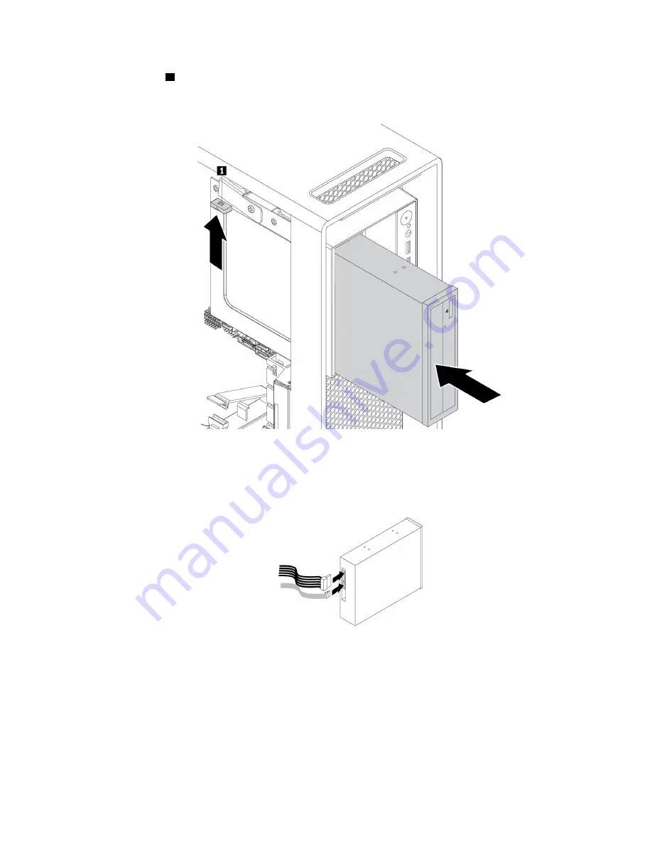
Lenovo ThinkStation P520 Скачать руководство пользователя страница 77

b.  Lift the tab 

upward as shown, and slide the new optical drive halfway into the bay from the front of 

the computer. Then, release the tabs and continue to slide the optical drive into the bay until it snaps 
into position.  

Figure 13. Installing the optical drive

c.  Connect the signal cable and the power cable to the new optical drive.  

Note:

Reconnect any cables removed from other supported devices.

Figure 14. Connecting cables to the optical drive

What to do next: 

•  To work with another piece of hardware, go to the appropriate section.

•  To complete the installation or replacement, go to “Completing the parts replacement” on page 134.

Storage drive in the front-access storage enclosure

Attention:

Do not open your computer or attempt any repair before reading and understanding the “Read 

this first: Important safety information” on page iii

Chapter 7

.

Hardware removal and installation

65

Содержание ThinkStation P520

Страница 1: ...P520 User Guide Machine Types 30BE 30BF 30BQ and 30DC ...

Страница 2: ...nformation on page iii and Appendix G Notices on page 157 Eighth Edition June 2020 Copyright Lenovo 2018 2020 LIMITED AND RESTRICTED RIGHTS NOTICE If data or software is delivered pursuant to a General Services Administration GSA contract use reproduction or disclosure is subject to restrictions set forth in Contract No GS 35F 05925 ...

Страница 3: ...ort 23 Accessibility information 24 Cleaning your computer 27 Maintenance 27 Basic maintenance tips 27 Good maintenance practices 27 Keeping your computer current 28 Moving your computer 28 Chapter 4 Security 29 Locking your computer 29 Locking the computer cover 29 Attaching a Kensington style cable lock 30 Viewing and changing security settings in the Setup Utility program 30 Using passwords and...

Страница 4: ...e drive in a storage drive bay 85 Storage drive cage 93 M 2 solid state drive 96 Power supply assembly 107 PCIe card 109 Full length PCIe card 115 Heat sink and fan assembly 118 Super capacitor module 119 Front fan assembly 121 Rear fan assembly 123 Memory module 124 Coin cell battery 126 Wi Fi units 127 Completing the parts replacement 134 Chapter 8 Getting information help and service 137 Inform...

Страница 5: ...structions when it is appropriate for customers to install options or replace CRUs You must closely follow all instructions when installing or replacing parts The Off state of a power indicator does not necessarily mean that voltage levels inside a product are zero Before you remove the covers from a product equipped with a power cord always ensure that the power is turned off and that the product...

Страница 6: ... it Do not place the part on the computer cover or other metal surface Power cords and power adapters Use only the power cords and power adapters supplied by the product manufacturer Do not use the ac power cord for other devices The power cords shall be safety approved For Germany it shall be H05VV F 3G 0 75 mm2 or better For other countries the suitable types shall be used accordingly Never wrap...

Страница 7: ... safety feature Never overload an electrical outlet The overall system load should not exceed 80 percent of the branch circuit rating Consult an electrician for more information if you have questions about power loads and branch circuit ratings Be sure that the power outlet you are using is properly wired easily accessible and located close to the equipment Do not fully extend power cords in a way...

Страница 8: ...high traffic areas Do not restrict or block any ventilation openings Do not store or operate your computer inside furniture as this might increase the risk of overheating Airflow temperatures into the computer should not exceed 35 C 95 F Do not install air filtration devices They may interfere with proper cooling Computer placement notices Inappropriate computer placement might cause harm to child...

Страница 9: ...GER Some laser products contain an embedded Class 3A or Class 3B laser diode Note the following Laser radiation when open Do not stare into the beam do not view directly with optical instruments and avoid direct exposure to the beam Hazardous energy statement DANGER Disconnect all power cords from electrical outlets before removing the computer cover or any part that has the above label attached D...

Страница 10: ...tor for earphones headphones or a headset However the headphone connector does not support the microphone of the headset If your computer has both a headset connector and an audio line out connector always use the headset connector for earphones headphones or a headset CAUTION Excessive sound pressure from earphones and headphones can cause hearing loss Adjustment of the equalizer to maximum incre...

Страница 11: ...nd pressure levels Cleaning and maintenance Keep your computer and workspace clean Shut down the computer and then disconnect the power cord before cleaning the computer Do not spray any liquid detergent directly on the computer or use any detergent containing flammable material to clean the computer Spray the detergent on a soft cloth and then wipe the computer surfaces Copyright Lenovo 2018 2020...

Страница 12: ...x P520 User Guide ...

Страница 13: ...overview This chapter provides basic information to help you get familiar with your computer Hardware locations This section provides information about the locations of your computer hardware Copyright Lenovo 2018 2020 1 ...

Страница 14: ...close button available on some models 2 Signal diagnostic LED indicator 3 Power button 4 Power indicator 5 Storage drive activity indicator 6 Photoelectric sensor 7 Headset connector 8 USB 3 0 connectors 4 9 SD card slot 1 Optical drive eject close button available on some models Press the button to eject or close the tray of the optical drive 2 P520 User Guide ...

Страница 15: ...he internal storage drives such as hard disk drives or solid state drives On The storage drives are active and data is being transferred Off when the computer is powered on No data is being transferred or the storage drives are not in use 6 Photoelectric sensor This sensor receives the flash light sent by the Lenovo PC Diagnostics application installed in the smartphone Then the photoelectric sens...

Страница 16: ...ghtly different from the illustration Figure 2 Rear view 1 PS 2 mouse connector 2 PS 2 keyboard connector 3 Optional serial connector 4 Ethernet connector 5 USB 3 0 connectors 4 6 USB 2 0 connectors 2 7 Microphone connector 8 Audio line out connector 9 Audio line in connector 10 Power cord connector 11 Security lock slot 12 Key nest slots 13 PCI PCIe card area 4 P520 User Guide ...

Страница 17: ...ctor to attach a high performance monitor a direct drive monitor or other compatible devices The Mini DisplayPort connector is a miniaturized version of a DisplayPort connector 1 PS 2 mouse connector Use this connector to attach a Personal System 2 PS 2 mouse a trackball or other pointing devices 2 PS 2 keyboard connector Use this connector to attach a PS 2 keyboard 3 Optional serial connector Use...

Страница 18: ... is established between the audio line out connector of the device and the audio line in connector of the computer 10 Power cord connector Connect the power cord to your computer for power supply 11 Security lock slot Attach a Kensington style cable lock to the security lock slot to secure your computer For more information see Attaching a Kensington style cable lock on page 30 12 Key nest slots I...

Страница 19: ... the computer cover on page 59 Figure 3 Component locations 1 Heat sink and fan assembly 2 Memory modules 3 Flex bays 4 Storage drive cage 5 Front fan assembly 6 Storage drives 7 M 2 solid state drives 8 Power supply assembly 9 PCI PCIe card 10 Rear fan assembly 11 Cover presence switch also called intrusion switch Configuration varies by computer models Chapter 1 Product overview 7 ...

Страница 20: ...lot 3 Memory slot 4 Rear fan assembly connector 5 Memory slot 6 Memory slot 7 Microprocessor fan connector 8 Memory slot 9 Memory slot 10 Optical drive fan connector 1 11 Optical drive fan connector 2 12 Memory slot 13 Memory slot 14 Thermal sensor connector 15 4 pin power connector for optical drive 16 Clear CMOS Recovery jumper 17 VROC connector 18 Front panel input output FPIO connector 8 P520 ...

Страница 21: ...30 SATA 6 connector 31 SATA 1 connector 32 SATA 4 connector 33 Internal USB 3 0 connector 2 34 Internal USB 3 0 connector 1 35 SATA 5 connector 36 Four digit diagnostics display connector 37 eSATA SATA 7 connector 38 Internal USB 2 0 connector 39 Trusted cryptography module TCM connector 40 Power supply connector 41 PCIe 3 0 x4 card slot 42 PCI card slot 43 PCIe 3 0 x16 card slot 44 PCIe 3 0 x4 ca...

Страница 22: ...apter 7 Hardware removal and installation on page 59 for instructions on how to remove or install internal storage drives for your computer The following illustration shows the locations of the storage drive bays Note The computer hardware might look slightly different from the illustration Figure 5 Storage drive bay locations 1 Card reader for an SD card 2 Flex bays 2 3 Storage drive bays 2 avail...

Страница 23: ...n the multi drive conversion kit Storage drive such as hard disk drive solid state drive or hybrid drive Slim optical drive Optical drive Slim optical drive adapter 3 Optional storage drive bays 2 available on some models You can install hard disk drives solid state drives or hybrid drives in the storage drive bays 4 Storage drive bays 2 You can install hard disk drives solid state drives or hybri...

Страница 24: ... computer model some features might vary or not apply Information about your computer To view basic information such as microprocessor and memory information about your computer do the following 1 Click the Start button to open the Start menu 2 Click Settings System About To view detailed information about the devices such as the optical drive and network adapters on your computer do the following...

Страница 25: ...x16 card slots on the system board for a discrete graphics card Video connectors on a discrete graphics card DVI connector available on some models DisplayPort connector available on some models Mini DisplayPort connector available on some models Audio features Integrated audio controller supports the following connectors and devices on your computer Audio line in connector Audio line out connecto...

Страница 26: ...Enabling or disabling the ErP LPS compliance mode on page 36 Intel Standard Manageability ISM Intel Standard Manageability builds certain functionalities into computer hardware and firmware Therefore computers are less expensive for businesses and easier to monitor maintain update upgrade and repair Intel Active Management Technology Intel AMT With specific Intel platform capabilities and third pa...

Страница 27: ...gram BIOS passwords and Windows accounts to deter unauthorized use of your computer Computrace Agent software embedded in firmware Cover presence switch also called intrusion switch Finger authentication available on some models Firewalls Intel BIOS guard Smart USB Protection function Startup sequence control Startup without a keyboard or mouse Support for a key lock on the computer cover availabl...

Страница 28: ...e the program name into the search box next to the Start button 2 In the search results click the name of the desired program to launch the program From the Start menu or Control Panel 1 Click the Start button to open the Start menu Then click the name of the desired program to launch the program 2 If the program name is not displayed on the Start menu access the program from Control Panel a Click...

Страница 29: ...er Guide and helpful articles Notes The available features vary depending on the computer model Lenovo Vantage makes periodic updates of the features to keep improving your experience with your computer The description of features might be different from that on your actual user interface ThinkStation Diagnostics The ThinkStation Diagnostics program enables you to troubleshoot and resolve computer...

Страница 30: ...18 P520 User Guide ...

Страница 31: ... notification area add the icon to the notification area See the Windows help system 2 Follow the instructions on the screen and the hover text to adjust the volume mute the speaker or unmute the speaker Using a disc This section provides instructions on how to use a disc and the optical drive Guidelines about using the optical drive When using the optical drive follow these guidelines Do not plac...

Страница 32: ...tton on the front of the optical drive The tray slides out of the drive 2 Carefully remove the disc from the tray 3 Press the eject close button again or gently push the tray forward to close the tray Note If the tray does not slide out of the drive when you press the eject close button turn off your computer Then insert a straightened paper clip into the emergency eject hole adjacent to the eject...

Страница 33: ...ss LAN feature is available only on some models To establish a wireless LAN connection do the following 1 Ensure that a wireless LAN is available and the wireless LAN feature on your computer is working 2 Click the wireless network connection status icon in the Windows notification area to display available wireless networks Note If the wireless network connection status icon is not displayed in t...

Страница 34: ...tion area on the taskbar Then click Add a Device and follow the instructions on the screen Note If the Bluetooth icon is not displayed in the Windows notification area add the icon to the notification area See the Windows help system 22 P520 User Guide ...

Страница 35: ... an antiglare filter placed over the screen might be helpful However these filters might affect the clarity of the image on the screen try them only after you have exhausted other methods of reducing glare Air circulation Your computer produces heat The computer has a fan that pulls in fresh air and forces out hot air through the air vents Blocking the air vents can cause overheating which might r...

Страница 36: ...ng users who have hearing vision and mobility limitations with greater access to information and technology This section provides information about the ways these users can get the most out of their computer experience You also can get the most up to date accessibility information from the following Web site https www lenovo com accessibility Keyboard shortcuts The following list contains keyboard...

Страница 37: ...tain key combinations easier Personalized mouse Adjust mouse settings to make your mouse easier to use For example you can change the pointer appearance and make it easier to manage windows with the mouse Speech Recognition Speech Recognition enables you to control your computer by voice Using only your voice you can start programs open menus click objects on the screen dictate text into documents...

Страница 38: ... or the minus sign key to reduce the text size Change the size of the items on the desktop or a window Note This function might not work on some windows If your mouse has a wheel press and hold Ctrl and then scroll the wheel to change the item size Industry standard connectors Your computer provides industry standard connectors that enable you to connect assistive devices For more information abou...

Страница 39: ...uter functioning properly Keep your computer in a clean dry environment Ensure that the computer rests on a flat steady surface Do not cover any of air vents These air vents provide airflow to keep your computer from overheating Keep food and drinks away from all parts of your computer Food particles and spills might make the keyboard and mouse stick and unusable Do not get the power switches or o...

Страница 40: ...es new versions of Windows components and device driver updates 1 Click the Start button to open the Start menu 2 Click Settings Update Security Windows Update 3 Follow the instructions on the screen Note The device drivers provided by Windows Update might not be tested by Lenovo It is recommended that you get device drivers by using Lenovo programs or from the Lenovo Web site at https support len...

Страница 41: ... computer cover helps prevent unauthorized people from gaining access to the inside of your computer Your computer might come with a key lock that is built into the computer cover The keys for the key lock are attached to the rear of the machine For security store the keys in a secure place when you are not using them Lenovo does not accept responsibility for any loss of keys Note The key lock and...

Страница 42: ... settings in the Setup Utility program do the following 1 Start the Setup Utility program See Starting the Setup Utility program on page 35 2 Select Security 3 Follow the instructions on the right side of the screen to view and change security settings You can refer to Using the Setup Utility program on page 35 to get basic information about some major security settings 4 To save settings and exit...

Страница 43: ...he system board first To achieve this do the following 1 Start the Setup Utility program See Starting the Setup Utility program on page 35 2 Select Security Chassis Intrusion Detection and press Enter 3 Select Enabled and press Enter 4 To save settings and exit the Setup Utility program press F10 or Fn F10 depending on the keyboard settings select Yes in the window displayed and press Enter The co...

Страница 44: ...he following modes Disabled default setting You can use the USB storage devices without limitation Read Only You cannot copy data from the computer to the USB storage devices However you can access or modify data on the USB storage devices No Access You cannot access the USB storage devices from the computer To configure the Smart USB Protection function do the following 1 Start the Setup Utility ...

Страница 45: ...Intel BIOS guard The BIOS guard module cryptographically verifies all the BIOS updates to the system BIOS flash Therefore the malware is blocked from attacking the BIOS Chapter 4 Security 33 ...

Страница 46: ...34 P520 User Guide ...

Страница 47: ...formation see Using BIOS passwords on page 37 To view and change the configuration settings follow the instructions on the screen Changing the display mode of the Setup Utility program You can use the Setup Utility program in the graphic mode or the text mode according to your needs Text mode The keys on the keyboard used to perform various tasks are displayed at the bottom of the screen Note The ...

Страница 48: ...tic Power On and press Enter 3 Select the feature you want to enable or disable and press Enter 4 Select the desired setting and press Enter 5 To save settings and exit the Setup Utility program press F10 or Fn F10 depending on the keyboard settings Then select Yes in the window displayed and press Enter Enabling or disabling the ErP LPS compliance mode Lenovo computers meet the eco design require...

Страница 49: ...ility program press F10 or Fn F10 depending on the keyboard settings Then select Yes in the window displayed and press Enter To bypass the error message and log in to the operating system do one of the following Press F2 or Fn F2 depending on the keyboard settings Start and then exit the Setup Utility program See Starting the Setup Utility program on page 35 and Exiting the Setup Utility program o...

Страница 50: ...events unauthorized access to the data on the internal storage drive such as a hard disk drive When a hard disk password is set you are prompted to enter a valid password each time you try to access the storage drive Notes Even if the storage drive is removed from one computer and installed in another the hard disk password is still valid If the hard disk password is forgotten there is no way to r...

Страница 51: ...er and connect the power cord See Chapter 7 Hardware removal and installation on page 59 6 Turn on the computer and leave it on for approximately 10 seconds Then turn off the computer by holding the power button for approximately five seconds 7 Repeat step 1 and step 2 8 Move the Clear CMOS Recovery jumper back to the standard position pin 1 and pin 2 9 Reinstall the computer cover and connect the...

Страница 52: ...anent startup device see Changing the startup device sequence permanently on page 39 Changing the fan speed level The Fan Control Stepping item enables you to adjust the thermal performance of your computer From level 1 to level 7 a higher fan speed level indicates better thermal performance with more noise To change the fan speed level do the following 1 Start the Setup Utility program See Starti...

Страница 53: ...n the system board See Hardware locations on page 1 4 Remove any parts and cables that impede your access to the Clear CMOS Recovery jumper 5 Move the jumper from the standard position pin 1 and pin 2 to the maintenance position pin 2 and pin 3 6 Reinstall the parts and cables that were removed 7 Reinstall the computer cover and reconnect any cables that were disconnected See Chapter 7 Hardware re...

Страница 54: ...he sections below to configure RAID with Intel RSTe Storage drive requirements for RAID levels Your computer supports the following RAID levels RAID 0 striped disk array Consists of at least two SATA storage drives Supported strip size 4 KB 8 KB 16 KB 32 KB 64 KB or 128 KB Better performance without fault tolerance RAID 1 mirrored disk array Consists of two SATA storage drives Improved reading per...

Страница 55: ...n the keyboard settings select Yes in the window displayed and press Enter Viewing the information about a RAID volume To view the information about a RAID volume do the following 1 Start the Setup Utility program See Starting the Setup Utility program on page 35 2 Select Advanced Intel RSTe SATA Controller and press Enter 3 Select RAID Volumes and press Enter 4 Select a RAID volume and press Ente...

Страница 56: ...three SATA or SAS storage drives Supported strip size 64 KB 128 KB 256 KB 512 KB or 1 MB Better performance and fault tolerance Available only on some models of AVAGO MegaRAID adapters RAID 6 block level striped disk array with dual distributed parity Consists of at least four SATA or SAS storage drives Supported strip size 64 KB 128 KB 256 KB 512 KB or 1 MB Better performance and fault tolerance ...

Страница 57: ...RAID volume do the following 1 Start the Setup Utility program See Starting the Setup Utility program on page 35 2 Select Advanced AVAGO MegaRAID Configuration Utility and press Enter 3 Select Main Menu and press Enter 4 Select Virtual Drive Management and press Enter 5 Select a RAID volume and press Enter to view the detailed information Deleting a RAID volume Attention All the existing data stor...

Страница 58: ... a RAID volume Attention All the existing data stored on the selected drives will be erased while the RAID volume is being created To create a RAID volume do the following 1 Enable VMD for the selected M 2 solid state drives by doing the following a Start the Setup Utility program See Starting the Setup Utility program on page 35 b Select Advanced Intel R VMD technology and press Enter c Select ea...

Страница 59: ...lowing 1 Start the Setup Utility program See Starting the Setup Utility program on page 35 2 Select Advanced Intel Virtual RAID on CPU and press Enter 3 Select RAID Volumes and press Enter 4 Select a RAID volume and press Enter to view the detailed information Deleting a RAID volume Attention All the existing data stored on the selected drives will be erased after you delete RAID volumes To delete...

Страница 60: ...48 P520 User Guide ...

Страница 61: ... the type of problem you are experiencing If these troubleshooting instructions do not resolve your problem continue with the next step 4 Run the diagnostic program See Diagnosing problems on page 56 If the diagnostic program does not resolve your problem continue with the next step 5 Recover your operating system See Recovery information on page 58 6 If none of these actions solve your problem co...

Страница 62: ...or some computers that have a front audio panel ensure that the volume is not set too low Ensure that your external speakers and headphones if used are connected to the correct audio connectors on the computer Most speaker cables are color coded to match the connectors Note When external speaker or headphone cables are connected to the audio connectors the internal speaker if present is disabled I...

Страница 63: ...op priority of the Boot Priority Order in the Setup Utility program Refer to Selecting a temporary startup device on page 40 for information about viewing and changing the startup sequence Note On some computer models the startup sequence is permanently set and cannot be changed A black screen is displayed instead of the DVD video Solutions Restart the DVD player program Try a lower screen resolut...

Страница 64: ...Some or all storage drives are missing from the Setup Utility program Solutions Ensure that the signal cables and power cables for all the storage drives are connected correctly If the computer is installed with SAS storage drives ensure that the AVAGO MegaRAID adapter is correctly connected The computer cannot start up from the correct storage drive or the message No Operating System Found is dis...

Страница 65: ...ub switch not 100 BASE X A Gigabit Ethernet model computer should connect to the network at a speed of 1000 Mbps but at only a speed of 100 Mbps Solutions Try another cable Set the link partner to auto negotiate Set the switch to be 802 3ab compliant gigabit over copper The Wake On LAN feature does not work Solution Enable the Wake On LAN feature in the Setup Utility program Wireless LAN problem N...

Страница 66: ...et or headphones Solution Set the Bluetooth headset or headphones as the default device 1 Exit the application that uses the sound device for example Windows Media Player 2 Right click the volume icon in the Windows notification area on the taskbar Note If the volume icon is not displayed in the Windows notification area add the icon to the notification area See the Windows help system 3 Click Pla...

Страница 67: ...turn some Windows features off click Turn Windows features on or off Follow the instructions on the screen To remove some unnecessary programs select the program you want to remove and then click Uninstall Change or Uninstall The free memory space is insufficient Solutions Right click a blank area on the taskbar and open Task Manager Then end some tasks you are not performing Install additional me...

Страница 68: ...World Wide Web Some programs do not work as expected Solutions 1 Check whether the problem is caused by a program a Ensure that the software is compatible with your computer Refer to the information supplied with the software for more information b Verify that other software works properly on your computer c Verify that the software you are using works on another computer 2 If the problem is cause...

Страница 69: ...ables your computer to monitor hardware components in real time for potential issues or errors without impacting the performance When an issue or error is detected hardware diagnostic information is presented in either of the following ways If the ThinkStation Diagnostics application is installed and running on your computer an issue or error message is displayed in the Windows notification area G...

Страница 70: ...e your files from a backup Note If you use the File History tool to restore your files from a backup ensure that you backed up your data earlier with the tool 1 Click the Start button to open the Start menu 2 Click Windows System Control Panel 3 View Control Panel by Large icons or Small icons and then click File History Restore personal files 4 Follow the instructions on the screen Use the Window...

Страница 71: ...stall or replace a new part When possible remove the new part from the static protective package and install it directly in the computer without setting the part down When this is not possible place the static protective package on a smooth level surface and place the part on the package Do not place the part on the computer cover or other metal surface Preparing your computer and removing the com...

Страница 72: ...3 Press the handle of the computer cover so that the handle is lifted Figure 9 Opening the handle on the computer cover 60 P520 User Guide ...

Страница 73: ...me with the CRU or will come a few days after the CRU arrives Removing and installing hardware This section provides instructions on how to remove and install hardware for your computer You can expand the capabilities of your computer and maintain your computer by removing or installing hardware Attention Do not open your computer or attempt any repair before reading and understanding the Read thi...

Страница 74: ...storage enclosure Multi drive conversion kit Optical drive Slim optical drive adapter Storage drive bracket Note The following instructions on how to remove or install an optical drive also apply to other supported devices in the flex bay To remove or install an optical drive do the following 1 Prepare your computer See Preparing your computer and removing the computer cover on page 59 2 Locate th...

Страница 75: ... 1 upward as shown and push the rear of the optical drive to slide it out of the computer Figure 11 Removing the optical drive 4 To install an optical drive do the following Chapter 7 Hardware removal and installation 63 ...

Страница 76: ... bay with a plastic shield installed press the clip as shown to remove the plastic shield If there is a metal static shield installed in the flex bay remove the metal static shield Figure 12 Removing the plastic shield in the flex bay 64 P520 User Guide ...

Страница 77: ... Reconnect any cables removed from other supported devices Figure 14 Connecting cables to the optical drive What to do next To work with another piece of hardware go to the appropriate section To complete the installation or replacement go to Completing the parts replacement on page 134 Storage drive in the front access storage enclosure Attention Do not open your computer or attempt any repair be...

Страница 78: ...formation The operating system of your computer does not reside on the storage drive installed in the front access storage enclosure Attention If any of the above requirements are not met do not remove or install the storage drive when the computer is turned on Otherwise data on the storage drive might get damaged 3 5 inch storage drive To remove or install a 3 5 inch storage drive do the followin...

Страница 79: ...3 5 inch storage drive flex both sides of the bracket to remove the 3 5 inch storage drive from the bracket Figure 17 Removing the 3 5 inch storage drive from the bracket Chapter 7 Hardware removal and installation 67 ...

Страница 80: ...ng the 3 5 inch storage drive into the bracket 6 Slide the bracket with the new 3 5 inch storage drive into the front access storage enclosure until it snaps into position Press the notch to secure the enclosure cover and lock the enclosure cover with the key Figure 19 Installing the 3 5 inch storage drive into the front access storage enclosure What to do next To work with another piece of hardwa...

Страница 81: ...n the enclosure cover Figure 20 Opening the front access storage enclosure cover 3 Press the pit on the bracket cover and then grasp the tilted cover to pull the bracket out of the front access storage enclosure Figure 21 Removing the bracket from the front access storage enclosure 4 To remove the 2 5 inch storage drive do the following a Flex both sides of the bracket to remove the 2 5 inch stora...

Страница 82: ... the bracket Figure 24 Removing the storage drive from the metal bracket 5 To install a new 2 5 inch storage drive into the front access storage enclosure do the following a Carefully flex both sides of the metal bracket and align the four tabs 1 on the metal bracket with the corresponding holes in the new storage drive Note Ensure that the connectors of the storage drive face toward the tab of th...

Страница 83: ... bracket into the plastic frame of the converter c Push the metal bracket down until the tab 1 is slightly curved Then push the bracket with the storage drive forward as shown until the tab 1 snaps into position Figure 27 Installing the metal bracket into the plastic frame of the converter Chapter 7 Hardware removal and installation 71 ...

Страница 84: ...storage drive into the front access storage enclosure until it snaps into position Press the notch to secure the enclosure cover and lock the enclosure cover with the key Figure 29 Installing the bracket with the 2 5 inch storage drive into the front access storage enclosure What to do next To work with another piece of hardware go to the appropriate section To complete the installation or replace...

Страница 85: ...the computer cover on page 59 2 Ensure that all the cables are disconnected from the kit Remove the kit from the front of the computer See Device in the flex bay on page 62 3 To remove the slim optical drive from the kit do the following a Press the clip through the hole in the top of the kit as shown and push forward the slim optical drive Then remove the slim optical drive out of the kit Figure ...

Страница 86: ...kit 5 Slide the kit into the flex bay and reconnect the cables What to do next To work with another piece of hardware go to the appropriate section To complete the installation or replacement go to Completing the parts replacement on page 134 3 5 inch storage drive To remove or install a 3 5 inch storage drive do the following 1 Prepare your computer See Preparing your computer and removing the co...

Страница 87: ...it Figure 34 Opening the rear cover of the kit 4 Press both clips simultaneously toward each other and pull the conversion bracket out of the rear of the kit Figure 35 Removing the conversion bracket from the kit Chapter 7 Hardware removal and installation 75 ...

Страница 88: ... on the drive Figure 36 Removing the 3 5 inch storage drive from the conversion bracket 6 To install a 3 5 inch storage drive ensure that the conversion bracket is unfolded To unfold the bracket do the following a Remove pins 1 and install them into slots 2 Figure 37 Removing pins and installing them into the new slots 76 P520 User Guide ...

Страница 89: ...se tabs 1 2 and 3 from the corresponding slots Figure 38 Releasing tabs from the corresponding slots c Unfold the bracket as shown Figure 39 Unfolding the bracket Chapter 7 Hardware removal and installation 77 ...

Страница 90: ... drive into the conversion bracket do the following a Flex both sides of the bracket and align pins 1 2 3 and 4 on the bracket with the corresponding holes in the new 3 5 inch storage drive b Install the new 3 5 inch storage drive into the bracket Do not touch the circuit board 5 on the drive Figure 41 Installing the new 3 5 inch storage drive into the bracket 78 P520 User Guide ...

Страница 91: ...ay and reconnect the cables What to do next To work with another piece of hardware go to the appropriate section To complete the installation or replacement go to Completing the parts replacement on page 134 2 5 inch storage drive To remove or install a 2 5 inch storage drive do the following 1 Prepare your computer See Preparing your computer and removing the computer cover on page 59 2 Ensure th...

Страница 92: ...pull the conversion bracket out of the rear of the kit Figure 45 Removing the conversion bracket from the kit 5 To remove the 2 5 inch storage drive flex both sides of the conversion bracket and then remove the drive out of the bracket Do not touch the circuit board on the drive Figure 46 Removing the 2 5 inch storage drive from the bracket 80 P520 User Guide ...

Страница 93: ...ing a Remove pins 1 and install them into slots 2 Figure 47 Removing pins and installing them into the new slots b Pivot the bracket as shown to release tabs 1 2 and 3 from the slots Figure 48 Pivoting the bracket c Fold the bracket as shown Figure 49 Folding the bracket Chapter 7 Hardware removal and installation 81 ...

Страница 94: ...ge drive into the conversion bracket do the following a Flex both sides of the bracket and align pins 1 2 3 and 4 on the bracket with the corresponding holes in the new 2 5 inch storage drive b Install the new 2 5 inch storage drive into the bracket Do not touch the circuit board 5 on the drive Figure 51 Installing the new 2 5 inch storage drive into the bracket 82 P520 User Guide ...

Страница 95: ... to do next To work with another piece of hardware go to the appropriate section To complete the installation or replacement go to Completing the parts replacement on page 134 Cover presence switch Attention Do not open your computer or attempt any repair before reading and understanding the Read this first Important safety information on page iii To remove or install the cover presence switch do ...

Страница 96: ...w cover presence switch with the two tabs on the computer chassis Then push the new cover presence switch inward until it is seated securely between the tabs Figure 55 Installing the cover presence switch b Connect the cable of the new cover presence switch to the cover presence switch connector on the system board See Parts on the system board on page 8 What to do next To work with another piece ...

Страница 97: ... Locate the storage drive bay See Internal storage drives on page 10 3 Ensure that all the cables are disconnected from the storage drive Press both clips simultaneously toward each other and pull the conversion bracket out of the storage drive bay Figure 56 Removing the conversion bracket 4 Flex both sides of the conversion bracket to remove the 3 5 inch storage drive from the bracket Do not touc...

Страница 98: ...ded To unfold the bracket do the following a Remove the pin 1 and install it into the slot 2 Figure 58 Removing the pin and installing it into the new slot b Release tabs 1 2 and 3 from the corresponding slots Figure 59 Releasing tabs from the corresponding slots 86 P520 User Guide ...

Страница 99: ...n Figure 60 Unfolding the bracket d Insert tabs 1 2 and 3 into the corresponding slots Ensure that the tabs are secured in place Figure 61 Inserting tabs into the corresponding slots Chapter 7 Hardware removal and installation 87 ...

Страница 100: ...h the circuit board 5 on the drive Figure 62 Installing the new 3 5 inch storage drive into the bracket 7 Ensure that the connectors on the storage drives are on the upper side Then slide the new 3 5 inch storage drive with the conversion bracket into the storage drive bay until the drive snaps into position Figure 63 Installing the new 3 5 inch storage drive with bracket into the storage drive ba...

Страница 101: ...age drive bay See Internal storage drives on page 10 3 Ensure that all the cables are disconnected from the storage drive Press both clips simultaneously toward each other and pull the conversion bracket out of the storage drive bay Figure 64 Removing the conversion bracket 4 Flex both sides of the conversion bracket to remove the 2 5 inch storage drive from the bracket Figure 65 Removing the stor...

Страница 102: ...n 1 and install it into the slot 2 Figure 66 Removing the pin and installing it into the new slot b Pivot the bracket as shown to release tabs 1 2 and 3 from the slots Figure 67 Pivoting the bracket 90 P520 User Guide ...

Страница 103: ...Figure 68 Folding the bracket d Insert tabs 1 2 and 3 into the corresponding slots Ensure that the tabs are secured in place Figure 69 Inserting the tabs into the corresponding slots Chapter 7 Hardware removal and installation 91 ...

Страница 104: ...h the circuit board on the drive Figure 70 Installing the new 2 5 inch storage drive into the bracket 7 Ensure that the connectors on the storage drives are on the upper side Slide the conversion bracket with the new 2 5 inch storage drive into the storage drive bay until it snaps into position Figure 71 Installing the storage drive with conversion bracket into the storage drive bay 8 Connect the ...

Страница 105: ...ring your computer and removing the computer cover on page 59 2 Remove the front fan assembly See Front fan assembly on page 121 3 Locate the storage drive cage See Computer components on page 7 4 Ensure that all the cables are disconnected from the storage drives Slide the storage drives out of the chassis See Storage drive in a storage drive bay on page 85 5 To remove the storage drive cage do t...

Страница 106: ...hassis Figure 73 Removing the storage drive cage 6 To install a storage drive cage do the following a Place the upper edge of the storage drive cage under the front fan assembly retainer as shown Figure 74 Placing the upper edge of the storage drive cage under the retainer 94 P520 User Guide ...

Страница 107: ...is snap in position Then install the three screws into the aligned screw holes to secure the storage drive cage Figure 76 Securing the storage drive cage with three screws 7 Slide the storage drives into the storage drive cage Reconnect the removed cables to the storage drives See Storage drive in a storage drive bay on page 85 8 Reinstall the front fan assembly Chapter 7 Hardware removal and inst...

Страница 108: ...d or on an M 2 solid state drive PCIe adapter The instructions on how to install or replace a M 2 solid state drive also apply to the Intel Optane memory Before replacing the Intel Optane memory ensure that you disable the Intel Optane memory from the Intel Rapid Storage Technology Intel RST Console Otherwise all data on the storage drive will be lost M 2 solid state drive in the storage drive bra...

Страница 109: ...he storage drive bracket Then grasp the M 2 solid state drive carrier by its edge and gently pull it out of the bracket Figure 77 Removing the M 2 solid state drive carrier b Remove two screws and slide the cover as shown to remove the cover from the carrier Figure 78 Removing the cover of the M 2 solid state drive carrier Chapter 7 Hardware removal and installation 97 ...

Страница 110: ... of the M 2 solid state drive Figure 79 Removing the M 2 solid state drive 3 To install the M 2 solid state drive do the following a Insert the new M 2 solid state drive into the slot at an angle of about 20 degrees Pivot the M 2 solid state drive downward Then tighten the screw to secure the M 2 solid state drive Figure 80 Installing the M 2 solid state drive 98 P520 User Guide ...

Страница 111: ...all the carrier into the bracket as shown until it snaps in to position Lock the carrier with the key Always store the key in a secure place Figure 82 Reinstalling the M 2 solid state drive carrier M 2 solid state drive on the system board To remove or install an M 2 solid state drive on the system board do the following Chapter 7 Hardware removal and installation 99 ...

Страница 112: ...ise to release the heat sink Then remove the heat sink from the system board Figure 83 Removing the heat sink 5 To remove the M 2 solid state drive do the following a Loosen the screw that secures the M 2 solid state drive 1 b Remove the M 2 solid state drive with the screw holder from the M 2 solid state drive slot 2 c Remove the screw holder from the M 2 solid state drive 3 Figure 84 Removing th...

Страница 113: ...rd side is facing upward Align the notch 1 in the new drive with the slot key 2 in the M 2 slot Insert the drive into the corresponding slot at an angle of about 20 degrees until it is firmly secured Pivot the M 2 solid state drive downward Notes Do not touch the circuit board of the M 2 solid state drive If only one M 2 solid state drive is installed ensure that the drive is installed in the M 2 ...

Страница 114: ...sary remove the film that protects the thermal pad on the heat sink Insert the two hooks on the heat sink into the corresponding holes as shown 1 Then press the heat sink downward 2 Ensure that the mounting stud on the heat sink is aligned with the hole in the system board Figure 88 Installing the heat sink onto the system board 102 P520 User Guide ...

Страница 115: ...lacement go to Completing the parts replacement on page 134 M 2 solid state drive in an M 2 solid state drive PCIe adapter Install M 2 solid state drives in the alphabetic order as shown Figure 90 M 2 solid state drive installation order To remove or install an M 2 solid state drive in the M 2 solid state drive PCIe adapter do the following 1 Remove the M 2 solid state drive PCIe adapter from the ...

Страница 116: ... position Then pivot the cover as shown until it stops Figure 91 Opening the cover 3 Loosen the screws that secure the M 2 solid state drive heat sink Then remove the heat sink as shown Figure 92 Removing the heat sink 104 P520 User Guide ...

Страница 117: ... state drive 5 To install an M 2 solid state drive do the following a If necessary move the retention latch to an appropriate location to suit the length of the new M 2 solid state drive Figure 94 Adjusting the location of the retention latch on the PCIe adapter b If necessary remove the film on the thermal pad on which you want to install the M 2 solid state drive Chapter 7 Hardware removal and i...

Страница 118: ...facing upward Align the notch in the new M 2 solid state drive with the slot key in the M 2 slot Insert the drive into the corresponding slot on the PCIe adapter until it is firmly seated Then insert the plug of the retention latch into the hole to secure the new drive Note Do not touch the circuit board of the M 2 solid state drive Figure 96 Installing the M 2 solid state drive 106 P520 User Guid...

Страница 119: ... card slot on the system board See Parts on the system board on page 8 and Full length PCIe card on page 115 What to do next To work with another piece of hardware go to the appropriate section To complete the installation or replacement go to Completing the parts replacement on page 134 Power supply assembly Attention Do not open your computer or attempt any repair before reading and understandin...

Страница 120: ...s designed for safe use However hazardous voltage current and energy levels are present inside any component that has this label attached Disassembling of these components might cause fire or might even result in death If you suspect a problem with one of these parts contact a service technician To remove or install the power supply assembly do the following 1 Prepare your computer See Preparing y...

Страница 121: ...o next To work with another piece of hardware go to the appropriate section To complete the installation or replacement go to Completing the parts replacement on page 134 PCIe card Attention Do not open your computer or attempt any repair before reading and understanding the Read this first Important safety information on page iii Your computer comes with the following combinations one standard PC...

Страница 122: ...a PCIe card also applies to the PCI card If your computer comes with a full length PCIe card refer to Full length PCIe card on page 115 for its replacement instructions To remove or install a PCIe card do the following 1 Prepare your computer See Preparing your computer and removing the computer cover on page 59 2 Lay the computer on its side for easier access to the system board 110 P520 User Gui...

Страница 123: ...e front fan assembly Gently pull the PCIe card retainer out of the slot in the front fan assembly and then remove the card retainer from the PCIe card latch Note The PCIe card retainer is only available on some models Figure 103 Removing the PCIe card retainer 4 To remove the PCIe card do the following Chapter 7 Hardware removal and installation 111 ...

Страница 124: ...e rear of the computer Then pivot the latch outward to rest it on the edge of the rear panel Figure 104 Opening the PCIe card latch b If the PCIe card is connected to another device disconnect the cable from the card first 112 P520 User Guide ...

Страница 125: ...l it out of the slot Note The card might fit tightly into the slot If necessary alternately move each side of the card a small amount until the card is removed from the slot Figure 105 Removing a PCIe card 5 To install a new PCIe card do the following a Remove the new PCIe card from its static protective package Chapter 7 Hardware removal and installation 113 ...

Страница 126: ...latch c Remove the appropriate metal slot cover Install the new card into the appropriate slot on the system board See Parts on the system board on page 8 d Pivot the PCIe card latch and push it back in until it snaps into position e If the new PCIe card needs to be connected to another device connect the cable of the device to the new PCIe card 114 P520 User Guide ...

Страница 127: ...eplacement go to Completing the parts replacement on page 134 Full length PCIe card Attention Do not open your computer or attempt any repair before reading and understanding the Read this first Important safety information on page iii Your computer comes with the following combinations one standard PCI card slot two PCIe 3 0 x4 card slots one PCIe 3 0 x8 card slot and two PCIe 3 0 x16 card slots ...

Страница 128: ...en pivot the latch outward to rest it on the edge of the rear panel Figure 108 Opening the PCIe card latch 4 Pull and pivot the tab on the front fan assembly as shown to open the latch inside Figure 109 Opening the latch in the front fan assembly 116 P520 User Guide ...

Страница 129: ...er b Remove the new full length PCIe card from its static protective package c Align the extender on the new full length PCIe card with the corresponding slot in the front fan assembly Then install the new card into the appropriate slot on the system board See Parts on the system board on page 8 Note It is recommended that you install the full length PCIe card into a PCIe 3 0 x16 card slot for bes...

Страница 130: ...ing your computer and removing the computer cover on page 59 2 Lay the computer on its side for easier access to the system board 3 Locate the heat sink and fan assembly See Computer components on page 7 4 Disconnect the heat sink and fan assembly cable from the microprocessor fan connector on the system board 5 Remove the four screws that secure the heat sink and fan assembly to the system board ...

Страница 131: ...ghten screw 3 10 Connect the heat sink and fan assembly cable to the microprocessor fan connector on the system board See Parts on the system board on page 8 What to do next To work with another piece of hardware go to the appropriate section To complete the installation or replacement go to Completing the parts replacement on page 134 Super capacitor module Attention Do not open your computer or ...

Страница 132: ...ive package that contains the new super capacitor module and its holder to any unpainted surface on the outside of the computer Then remove the new super capacitor module and its holder from the package b Pull and pivot the tab on the front fan assembly as shown to open the latch inside Figure 114 Opening the latch in the front fan assembly c Connect the super capacitor module cable to the super c...

Страница 133: ... your computer or attempt any repair before reading and understanding the Read this first Important safety information on page iii CAUTION Keep fingers and other parts of your body away from hazardous moving parts If you suffer an injury seek medical care immediately To remove or install the front fan assembly do the following 1 Prepare your computer See Preparing your computer and removing the co...

Страница 134: ...owing a Connect the cable of the new front fan assembly to the front fan assembly connector on the system board See Parts on the system board on page 8 b Align the top and bottom edges of the new front fan assembly with the front fan assembly retainer in the computer chassis Then slide the new front fan assembly inward until it is secured in position Figure 117 Installing the front fan assembly 5 ...

Страница 135: ...care immediately To remove or install the rear fan assembly do the following 1 Prepare your computer See Preparing your computer and removing the computer cover on page 59 2 Locate the rear fan assembly See Computer components on page 7 3 To remove the rear fan assembly do the following a Locate and disconnect the rear fan assembly cable from the rear fan assembly connector on the system board b R...

Страница 136: ...th another piece of hardware go to the appropriate section To complete the installation or replacement go to Completing the parts replacement on page 134 Memory module Attention Do not open your computer or attempt any repair before reading and understanding the Read this first Important safety information on page iii Your computer has eight slots for installing DDR4 RDIMMs that provide up to a ma...

Страница 137: ...oving the computer cover on page 59 2 Lay the computer on its side for easier access to the system board 3 Locate the memory module slot See Parts on the system board on page 8 4 To remove the memory module open the retaining clips and gently pull the memory module out of the memory slot Figure 121 Removing a memory module 5 To install a memory module do the following Chapter 7 Hardware removal an...

Страница 138: ...t on page 134 Coin cell battery Attention Do not open your computer or attempt any repair before reading and understanding the Read this first Important safety information on page iii Your computer has a special type of memory that maintains the date time and settings for built in features such as parallel connector assignments configuration A coin cell battery keeps this information active when y...

Страница 139: ... PCIe card on page 109 Full length PCIe card on page 115 or Super capacitor module on page 119 7 Reinstall the computer cover and connect the cables See Completing the parts replacement on page 134 Note When the computer is turned on for the first time after the coin cell battery is replaced an error message might be displayed This is normal after the coin cell battery is replaced 8 Turn on the co...

Страница 140: ...2 To remove the Wi Fi antenna unscrew the Wi Fi antenna cable from the rear of the computer Figure 126 Removing the Wi Fi antenna 128 P520 User Guide ...

Страница 141: ...e Bluetooth cable from the Wi Fi adapter Figure 127 Disconnecting the Bluetooth cable 4 To remove the Wi Fi adapter lift the plastic PCIe card latch at the rear of the computer Then pivot the latch outward to rest it on the edge of the rear panel Chapter 7 Hardware removal and installation 129 ...

Страница 142: ...Figure 128 Opening the PCIe card latch 130 P520 User Guide ...

Страница 143: ... it out of the slot Note The card might fit tightly into the slot If necessary alternately move each side of the card a small amount until the card is removed from the slot Figure 129 Removing the Wi Fi adapter Chapter 7 Hardware removal and installation 131 ...

Страница 144: ...ntly pull the Wi Fi card out of the mini PCIe slot Figure 130 Removing the Wi Fi card 6 To install a new Wi Fi card do the following a Insert the Wi Fi card into the mini PCIe slot on the Wi Fi adapter b Install the two screws to secure the Wi Fi card to the Wi Fi adapter c Connect the two Wi Fi antenna cables to the Wi Fi card Figure 131 Installing a Wi Fi card 132 P520 User Guide ...

Страница 145: ...it snaps into position Figure 132 Installing the Wi Fi adapter 8 If the installed Wi Fi card supports the Bluetooth function connect a Bluetooth cable to the Wi Fi adapter Note The Bluetooth cable connects the Bluetooth connector on the Wi Fi adapter to one of the internal USB 3 0 connectors on the system board See Parts on the system board on page 8 Chapter 7 Hardware removal and installation 133...

Страница 146: ...stall all protective covers including the computer cover before connecting power and operating the computer This action is important to help prevent unexpected electrical shock and help ensure the containment of an unexpected fire that could happen under extremely rare conditions After completing the installation or replacement for all parts reinstall the computer cover and reconnect cables Depend...

Страница 147: ...routed correctly before reinstalling the computer cover Keep cables clear of the hinges and sides of the computer chassis to avoid interference with reinstalling the computer cover 3 Hold the computer cover with the handle and position the computer cover on the chassis Insert the tabs on the bottom of the cover into the corresponding slots on the chassis Figure 134 Positioning the computer cover C...

Страница 148: ...vice available lock the computer cover See Locking your computer on page 29 7 Reconnect the external cables and power cords to the corresponding connectors on the computer See Hardware locations on page 1 8 Update the configuration of your computer if necessary See Using the Setup Utility program on page 35 9 If a newly installed hardware component does not work correctly update the device driver ...

Страница 149: ...safety information in the Safety Warranty and Setup Guide before using your computer In addition read and understand Read this first Important safety information on page iii before using your computer This preface provides additional safety information that applies to topics and tasks described in this User Guide Lenovo Web site The Lenovo Web site https www lenovo com provides up to date informat...

Страница 150: ... the warranty period Problem determination Trained service personnel are available to assist you with determining a hardware problem and deciding what action is necessary to fix the problem Hardware repair If the problem is caused by hardware under warranty trained service personnel are available to provide the applicable level of service Engineering Change management There might be changes that a...

Страница 151: ... restrictions might apply at the time of service To determine whether your computer is eligible for International Warranty Service and to view a list of the countries or regions where service is available go to https support lenovo com For technical assistance with the installation of or questions related to Service Packs for your preinstalled Microsoft Windows product go to https support microsof...

Страница 152: ...140 P520 User Guide ...

Страница 153: ... model and the type speed size capacity and number of DIMMs installed Notes The actual system memory speed of the memory modules varies depending on the microprocessor model For example your computer comes with 2666 MT s memory modules but microprocessor only supports up to 2400 MT s memory modules Then the system memory speed will be no faster than 2400 MT s The microprocessor models supported in...

Страница 154: ...142 P520 User Guide ...

Страница 155: ...vo office or reseller to obtain a printed version of the LLW Accessing the Ubuntu help system The Ubuntu help system provides information about how to use the Ubuntu operating system To access the help system from the Unity move your pointer to the Launch bar and then click the Help icon If you cannot find the Help icon from the Launch bar click the Search icon and type Help to search it To learn ...

Страница 156: ...144 P520 User Guide ...

Страница 157: ...e with the instructions may cause harmful interference to radio communications However there is no guarantee that interference will not occur in a particular installation If this equipment does cause harmful interference to radio or television reception which can be determined by turning the equipment off and on the user is encouraged to try to correct the interference by one or more of the follow...

Страница 158: ...atisfy the protection requirements resulting from a non recommended modification of the product including the installation of option cards from other manufacturers German Class B compliance statement Deutschsprachiger EU Hinweis Hinweis für Geräte der Klasse B EU Richtlinie zur Elektromagnetischen Verträglichkeit Dieses Produkt entspricht den Schutzanforderungen der EU Richtlinie 2014 30 EU zur An...

Страница 159: ...rät erfüllt die Schutzanforderungen nach EN 55024 und EN 55032 Klasse B Korean wireless radio compliance information Japan VCCI Class B compliance statement Japan compliance statement for products which connect to the power mains with rated current less than or equal to 20 A per phase Japan notice for ac power cord The ac power cord shipped with your product can be used only for this specific prod...

Страница 160: ...ar su operación no deseada Additional regulatory information For additional regulatory information refer to the Regulatory Notice shipped with your computer Depending on the configuration of your computer and the country or region where the computer was purchased you might have received additional printed regulatory notices All regulatory notices are available on the Lenovo Support Web site in ele...

Страница 161: ...E as unsorted municipal waste but use the collection framework available to them for the return recycle and recovery of WEEE and to minimize any potential effects of EEE on the environment and human health due to the presence of hazardous substances Lenovo electrical and electronic equipment EEE may contain parts and components which at end of life might qualify as hazardous waste EEE and waste el...

Страница 162: ...ttery is installed inside your Lenovo computer to provide power to the computer clock while the computer is off or disconnected from the main power source If you need to replace it with a new one contact your place of purchase or contact Lenovo for service If you need to dispose of a disused lithium battery insulate it with vinyl tape contact your place of purchase or an industrial waste disposal ...

Страница 163: ...s on the environment and human health due to the potential presence of hazardous substances Before placing electrical and electronic equipment EEE in the waste collection stream or in waste collection facilities the end user of equipment containing batteries and or accumulators must remove those batteries and accumulators for separate collection Disposing of lithium batteries and battery packs fro...

Страница 164: ...152 P520 User Guide ...

Страница 165: ...the restriction of the use of certain hazardous substances in electrical and electronic equipment RoHS recast or RoHS 2 For more information about Lenovo worldwide compliance on RoHS go to https www lenovo com rohs communication Turkish RoHS The Lenovo product meets the requirements of the Republic of Turkey Directive on the Restriction of the Use of Certain Hazardous Substances in Waste Electrica...

Страница 166: ...Mainland China RoHS Taiwan RoHS 154 P520 User Guide ...

Страница 167: ...f your computer you reduce the consumption of electricity Reduced electrical consumption contributes to potential financial savings a cleaner environment and the reduction of greenhouse gas emissions For more information about ENERGY STAR go to https www energystar gov Lenovo encourages you to make efficient use of energy an integral part of your day to day operations To help in this endeavor set ...

Страница 168: ...156 P520 User Guide ...

Страница 169: ...lication Lenovo may make improvements and or changes in the products and or the programs described in this publication at any time without notice The products described in this document are not intended for use in implantation or other life support applications where malfunction may result in injury or death to persons The information contained in this document does not affect or change Lenovo pro...

Страница 170: ...158 P520 User Guide ...

Страница 171: ... Thunderbolt and Xeon are trademarks of Intel Corporation in the U S and or other countries Linux is a registered trademark of Linus Torvalds DisplayPort and Mini DisplayPort are trademarks of the Video Electronics Standards Association Ubuntu is a registered trademark of Canonical Ltd All other trademarks are the property of their respective owners 2020 Lenovo Copyright Lenovo 2018 2020 159 ...

Страница 172: ...160 P520 User Guide ...

Страница 173: ......

Страница 174: ......

Отзывы: