Lenovo ThinkStation 4215 Скачать руководство пользователя страница 21

CUIDADO:

Ao substituir a bateria de lítio, utilize apenas uma bateria com Número de Peça
45C1566 ou um tipo de bateria equivalente recomendado pelo Se o seu sistema
possui um módulo com uma bateria de lítio, substitua-o apenas por um módulo
do mesmo tipo e do mesmo fabricante. A bateria contém lítio e pode explodir se
não for utilizada, manuseada ou descartada de maneira correta.

Não:

v

Jogue ou coloque na água

v

Aqueça a mais de 100°C (212°F)

v

Conserte nem desmonte

Descarte a bateria conforme requerido pelas leis ou regulamentos locais.

PRECAUCIÓN:

Quando produtos a laser (como unidades de CD-ROMs, unidades de DVD-ROM,
dispositivos de fibra ótica ou transmissores) estiverem instalados, observe o
seguinte:

v

Não remova as tampas. A remoção das tampas de um produto a laser pode
resultar em exposição prejudicial à radiação de laser. Não existem peças que
podem ser consertadas no interior do dispositivo.

v

A utilização de controles ou ajustes ou a execução de procedimentos diferentes
dos especificados aqui pode resultar em exposição prejudicial à radiação.

PERIGO

Alguns produtos a laser contêm diodo de laser integrado da Classe 3A ou da
Classe 3B. Observe o seguinte:

Radiação a laser quando aberto. Não olhe diretamente para o feixe a olho nu ou
com instrumentos ópticos e evite exposição direta ao feixe.
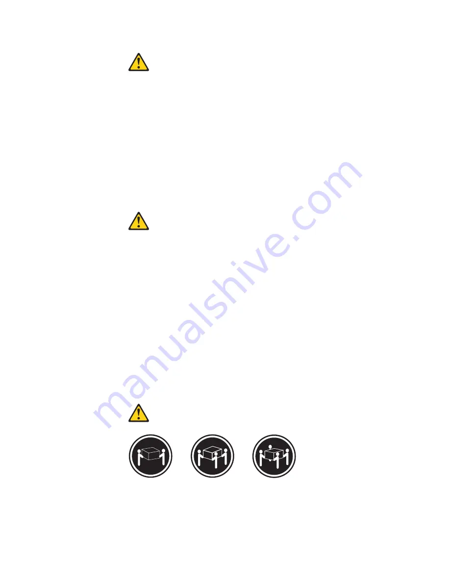
18 kg (37 lbs)

32 kg (70.5 lbs)

55 kg (121.2 lbs)

CUIDADO:

Utilize procedimentos de segurança para levantar equipamentos.

Chapter 2. Safety information

15

Содержание ThinkStation 4215

Страница 1: ......

Страница 2: ......

Страница 3: ...ThinkStation Hardware Maintenance Manual ...

Страница 4: ...ces have been developed exclusively at private expense and are sold to governmental entities as commercial items as defined by 48 C F R 2 101 with limited and restricted rights to use reproduction and disclosure LIMITED AND RESTRICTED RIGHTS NOTICE If products data computer software or services are delivered pursuant a General Services Administration GSA contract use reproduction or disclosure is ...

Страница 5: ...y program 52 Chapter 7 Configuring RAID 53 RAID Level 53 Configuring the system BIOS to enable SATA RAID functionality 53 Creating RAID volumes 53 Deleting RAID volumes 54 Chapter 8 Symptom to FRU Index 55 Hard disk drive boot error 55 Power Supply Problems 55 Diagnostic error codes 56 Beep symptoms 77 POST error codes 78 Miscellaneous error messages 80 Undetermined problems 81 Chapter 9 Replacing...

Страница 6: ...168 Updating flashing BIOS from your operating system 168 Recovering from a POST BIOS update failure 168 Power management 170 Automatic configuration and power interface ACPI BIOS 170 Automatic Power On features 170 Appendix Notices 171 Television output notice 172 Trademarks 172 iv Hardware Maintenance Manual ...

Страница 7: ...rnet access FRU part numbers are also available at http www lenovo com support Important Safety Information Be sure to read all caution and danger statements in this book before performing any of the instructions Veuillez lire toutes les consignes de type DANGER et ATTENTION du présent document avant d exécuter les instructions Lesen Sie unbedingt alle Hinweise vom Typ ACHTUNG oder VORSICHT in die...

Страница 8: ...te and expects its suppliers to be ready to support Lenovo s requirements and schedule in the EU Products sold in 2005 will contain some RoHS compliant FRUs The following statement pertains to these products and any product Lenovo produces containing RoHS compliant parts RoHS compliant ThinkStation parts have unique FRU part numbers Before or after June 2006 failed RoHS compliant parts must always...

Страница 9: ...el are not in a hazardous position v Place removed covers and other parts in a safe place away from all personnel while you are servicing the machine v Keep your tool case away from walk areas so that other people will not trip over it v Do not wear loose clothing that can be trapped in the moving parts of a machine Ensure that your sleeves are fastened or rolled up above your elbows If your hair ...

Страница 10: ... work on the machine unplug the power cord If you cannot unplug it ask the customer to power off the wall box that supplies power to the machine and to lock the wall box in the off position v If you need to work on a machine that has exposed electrical circuits observe the following precautions Ensure that another person familiar with the power off controls is near you Remember Another person must...

Страница 11: ... computer is designed to operate only at the voltage provided in the country or region where the computer was originally purchased If you relocate your computer to another country be aware of the following v If your computer does not have a voltage selection switch do not connect the computer to an electrical outlet until you have verified that the voltage provided is the same as it was in the cou...

Страница 12: ...5 Check for any obvious alterations Use good judgment as to the safety of any alterations 6 Check inside the unit for any obvious unsafe conditions such as metal filings contamination water or other liquids or signs of fire or smoke damage 7 Check for worn frayed or pinched cables 8 Check that the power supply cover fasteners screws or rivets have not been removed or tampered with Handling electro...

Страница 13: ...ells on these systems Use the round ground prong of the ac plug on ac operated computers Grounding requirements Electrical grounding of the computer is required for operator safety and correct system function Proper grounding of the electrical outlet can be verified by a certified electrician Safety notices multi lingual translations The caution and danger safety notices in this section are provid...

Страница 14: ... covers unless instructed otherwise in the installation and configuration procedures v Connect and disconnect cables as described in the following tables when installing moving or opening covers on this product or attached devices To Connect To Disconnect 1 Turn everything OFF 2 First attach all cables to devices 3 Attach signal cables to connectors 4 Attach power cords to outlet 5 Turn device ON ...

Страница 15: ...D ROMs DVD ROM drives fiber optic devices or transmitters are installed note the following v Do not remove the covers Removing the covers of the laser product could result in exposure to hazardous laser radiation There are no serviceable parts inside the device v Use of controls or adjustments or performance of procedures other than those specified herein might result in hazardous radiation exposu...

Страница 16: ...power supply do not turn off the electrical current supplied to the device The device also might have more than one power cord To remove all electrical current from the device ensure that all power cords are disconnected from the power source 1 2 10 Hardware Maintenance Manual ...

Страница 17: ...Chapter 2 Safety information 11 ...

Страница 18: ...12 Hardware Maintenance Manual ...

Страница 19: ... 18 kg 37 lbs 32 kg 70 5 lbs 55 kg 121 2 lbs 1 2 Chapter 2 Safety information 13 ...

Страница 20: ...dência de fogo água ou danos estruturais v Antes de abrir tampas de dispositivos desconecte cabos de alimentação sistemas de telecomunicação redes e modems conectados a menos que especificado de maneira diferente nos procedimentos de instalação e configuração v Conecte e desconecte os cabos conforme descrito na tabela apresentada a seguir ao instalar mover ou abrir tampas deste produto ou de dispo...

Страница 21: ...itivos de fibra ótica ou transmissores estiverem instalados observe o seguinte v Não remova as tampas A remoção das tampas de um produto a laser pode resultar em exposição prejudicial à radiação de laser Não existem peças que podem ser consertadas no interior do dispositivo v A utilização de controles ou ajustes ou a execução de procedimentos diferentes dos especificados aqui pode resultar em expo...

Страница 22: ...mentação não desligam a corrente elétrica fornecida ao dispositivo O dispositivo também pode ter mais de um cabo de alimentação Para remover toda a corrente elétrica do dispositivo assegure que todos os cabos de alimentação estejam desconectados da fonte de alimentação 1 2 16 Hardware Maintenance Manual ...

Страница 23: ...Chapter 2 Safety information 17 ...

Страница 24: ...1 2 18 Hardware Maintenance Manual ...

Страница 25: ...Chapter 2 Safety information 19 ...

Страница 26: ...1 2 20 Hardware Maintenance Manual ...

Страница 27: ...irer les carters de l unité mettez celle ci hors tension et déconnectez ses cordons d alimentation ainsi que les câbles qui la relient aux réseaux aux systèmes de télécommunication et aux modems sauf instruction contraire mentionnée dans les procédures d installation et de configuration v Lorsque vous installez que vous déplacez ou que vous manipulez le présent produit ou des périphériques qui lui...

Страница 28: ...n en vigueur ATTENTION Si des produits à laser tels que des unités de CD ROM de DVD ROM des unités à fibres optiques ou des émetteurs sont installés prenez connaissance des informations suivantes v Ne retirez pas le carter En ouvrant l unité de CD ROM ou de DVD ROM vous vous exposez au rayonnement dangereux du laser Aucune pièce de l unité n est réparable v Pour éviter tout risque d exposition au ...

Страница 29: ... d alimentation de l unité et l interrupteur dubloc d alimentation ne coupent pas le courant électrique alimentantl unité En outre le système peut être équipé de plusieurs cordonsd alimentation Pour mettre l unité hors tension vous devez déconnectertous les cordons de la source d alimentation 1 2 Chapter 2 Safety information 23 ...

Страница 30: ...rbindung zu den angeschlossenen Netzkabeln Telekommunikationssystemen Netzwerken und Modems ist vor dem Öffnen des Gehäuses zu unterbrechen sofern in den Installations und Konfigurationsprozeduren keine anders lautenden Anweisungen enthalten sind v Zum Installieren Transportieren und Öffnen der Abdeckungen des Computers oder der angeschlossenen Einheiten die Kabel gemäß der folgenden Tabelle ansch...

Страница 31: ...ermüll beachten ACHTUNG Bei der Installation von Lasergeräten wie CD ROM Laufwerken DVD aufwerken Einheiten mit Lichtwellenleitertechnik oder Sendern Folgendes beachten v Die Abdeckungen nicht entfernen Durch Entfernen der Abdeckungen des Lasergeräts können gefährliche Laserstrahlungen freigesetzt werden Das Gerät enthält keine zu wartenden Teile v Werden Steuerelemente Einstellungen oder Durchfüh...

Страница 32: ...zschalter an der Einheit und am Netzteil wird die Stromversorgung für die Einheit nicht unterbrochen Die Einheit kann auch mit mehreren Netzkabeln ausgestattet sein Um die Stromversorgung für die Einheit vollständig zu unterbrechen müssen alle zum Gerät führenden Netzkabel vom Netz getrennt werden 1 2 26 Hardware Maintenance Manual ...

Страница 33: ...Chapter 2 Safety information 27 ...

Страница 34: ...28 Hardware Maintenance Manual ...

Страница 35: ...1 2 Chapter 2 Safety information 29 ...

Страница 36: ...di incendi perdite d acqua o danno strutturale v Scollegare i cavi di alimentazione i sistemi di telecomunicazione le reti e il modem prima di aprire i coperchi del dispositivo salvo istruzioni contrarie relative alle procedure di installazione e configurazione v Collegare e scollegare i cavi come descritto nella seguente tabella quando vengono effettuate operazioni di installazione spostamento o ...

Страница 37: ...R 915 82 e successive disposizioni e disposizioni locali ATTENZIONE Quando vengono installati prodotti laser quali CD ROM unità DVD ROM unità a fibre ottiche o trasmittenti tener presente quanto segue v Non rimuovere gli sportelli L apertura di un unità laser può determinare l esposizione a radiazioni laser pericolose All interno dell unità non vi sono parti su cui effettuare l assistenza tecnica ...

Страница 38: ...entazione presente sull unità e l interruttore dell alimentatore non disattivano l alimentazione corrente fornita all unità E possibile che l unità disponga di più cavi di alimentazione Per disattivare l alimentazione dall unità accertarsi che tutti i cavi di alimentazione siano scollegati dalla fonte di alimentazione 1 2 32 Hardware Maintenance Manual ...

Страница 39: ...Chapter 2 Safety information 33 ...

Страница 40: ...1 2 34 Hardware Maintenance Manual ...

Страница 41: ... o daños estructurales v Desconecte los cables de alimentación los sistemas de telecomunicaciones las redes y los módems conectados antes de abrir las cubiertas de los dispositivos a menos que se indique lo contrario en los procedimientos de instalación y configuración v Conecte y desconecte los cables como se describe en la tabla siguiente cuando instale mueva o abra las cubiertas de este product...

Страница 42: ...ÓN Cuando haya productos láser como unidades de CD ROM unidades de DVD dispositivos de fibra óptica o transmisores instalados tenga en cuenta lo siguiente v No quite las cubiertas Si quita las cubiertas del producto láser podría quedar expuesto a radiación láser peligrosa Dentro del dispositivo no existe ninguna pieza que requiera servicio técnico v Si usa controles o ajustes o realiza procedimien...

Страница 43: ...interruptor de alimentación de la fuente de alimentación no desconectan la corriente eléctrica suministrada al dispositivo Además el dispositivo podría tener más de un cable de alimentación Para suprimir toda la corriente eléctrica del dispositivo asegúrese de que todos los cables de alimentación estén desconectados de la toma de corriente 1 2 Chapter 2 Safety information 37 ...

Страница 44: ...38 Hardware Maintenance Manual ...

Страница 45: ...be Reader program installation 2 The publications are available in other languages on the Lenovo Support Web site at http www lenovo com support 3 If you want to install a different language version of the Adobe Reader program rather than the version preinstalled on your computer download the language version you want from the Adobe Web site at http www adobe com Lenovo ThinkVantage Tools The Leno...

Страница 46: ... kg 24 7 lbs Environment Air temperature Operating 10 to 35 C 50 to 95 F Non operating 40 to 60 C 40 to 140 F with package Non operating 10 to 60 C 14 to 140 F without package Note The allowable upper temperature limit is lowered by 1 C 1 8 F for every 300 m 1000 ft above sea level Humidity Operating 20 to 80 non condensing Non operating 20 to 90 non condensing Maximum altitude Operating 0 to 10 0...

Страница 47: ...ices 5 Power on the computer v Look for displayed error codes v Listen for beep codes v Look for readable instructions or a main menu on the display If you did not receive the correct response proceed to step 6 If you do receive the correct response proceed to step 7 6 Look at the following conditions and follow the instructions v If you hear beep codes during POST go to Beep symptoms on page 77 v...

Страница 48: ...e confusion identical systems are considered identical only if they 1 Are the exact machine type and models 2 Have the same BIOS level 3 Have the same adapters attachments in the same locations 4 Have the same address jumpers terminators cabling 5 Have the same software versions and levels 6 Have the same diagnostic diskettes version 7 Have the same configuration options set in the system 8 Have t...

Страница 49: ...reinstalled with the Windows 7 operating system from Lenovo The Lenovo ThinkVantage Toolbox program helps you maintain your computer improve computing security diagnose computer problems get familiar with the innovative technologies provided by Lenovo and get more information about your computer You can use the Diagnostics feature of the Lenovo ThinkVantage Toolbox program to test devices diagnose...

Страница 50: ... for Rescue and Recovery diagnostic program refer to the PC Doctor for Rescue and Recovery help system Note If you encounter failures that prevent you from gaining access to the Rescue and Recovery workspace you can run the PC Doctor for Rescue and Recovery diagnostic program after using a rescue medium to recover the computer from failures and gaining access to the Rescue and Recovery workspace S...

Страница 51: ...ostics programs Use the cursor movement keys to navigate within the menus v The Enter key is used to select a menu item v The Esc key is used to back up to the previous menu v For online help select F1 Running tests There are four ways to run the diagnostic tests v Using the cursor movement keys highlight Run Normal Test or Run Quick Test from the Diagnostics menu and then press Enter This automat...

Страница 52: ...n the specified computer The diagnostic error code is recorded correctly v Text Description of the error Note See Diagnostic error codes on page 56 for error code listings Quick and Full erase hard disk drive The diagnostics program offers two hard disk drive formatting utilities v Quick Erase Hard Drive v Full Erase Hard Drive Quick Erase Hard Drive provides a DOS utility that performs the follow...

Страница 53: ... the QUICK ERASE or FULL ERASE HARD DISK option and follow the instructions on the screen Viewing the test log Errors reported by the diagnostic test will be displayed by the program as a failed test To view details of a failure or to view a list of test results use the following procedure from any test category screen 1 Press F3 to activate the log file 2 Press F3 again to save the file to disket...

Страница 54: ...48 Hardware Maintenance Manual ...

Страница 55: ...gram might start automatically when POST detects that hardware has been removed or new hardware has been installed in your computer Viewing and changing settings The Setup Utility program menu lists various items about the system configuration To view or change settings start the Setup Utility program See Starting the Setup Utility program Then follow the instructions on the screen When working wi...

Страница 56: ... an Administrator Password is set you are prompted to type a valid password each time you try to access the Setup Utility program The Setup Utility program cannot be accessed until a valid password is typed in If both the Power On Password and Administrator Password are set you can type either password However you must use your Administrator Password to change any configuration settings Hard Disk ...

Страница 57: ...sable do one of the following v Select USB Setup to enable or disable a USB device v Select ATA Drives Setup to enable or disable an internal or external SATA device 4 Select the desired settings and press Enter 5 Press F10 to save and exit the Setup Utility program See Exiting from the Setup Utility program on page 52 Selecting a startup device If your computer does not start up from a device suc...

Страница 58: ...systems such as the Windows 7 operating system and the Windows Vista operating system The default setting for HyperThreading is enabled However if you are not using a HyperThreading aware operating system and the setting for HyperThreading is Enabled your computer performance might be degraded Therefore you should always set HyperThreading to Disabled unless you are sure your operating system supp...

Страница 59: ...ng the system BIOS to enable SATA RAID functionality This section describes how to configure the system BIOS to enable SATA RAID functionality Note Use the arrow keys on the keyboard to make selections To enable SATA RAID functionality do the following 1 Start the Setup Utility program See Starting the Setup Utility program on page 49 2 Select Devices ATA Drives Setup 3 Select Configure SATA as an...

Страница 60: ...w keys to select Delete RAID Volume and press Enter 3 Use the arrow keys to select the RAID volume to be deleted and press Delete 4 When prompted press Y to confirm the deletion of the selected RAID volume Deleting a RAID volume will reset the hard disk drives to non RAID 5 After deleting a RAID volume you can v Return to step 2 to delete additional RAID volumes v See Creating RAID volumes on page...

Страница 61: ...d disk drive boot error can have the following causes Error FRU Action The start up drive is not in the boot sequence in configuration Check the configuration and ensure the start up drive is in the boot sequence No operating system installed on the boot drive Install an operating system on the boot drive The boot sector on the start up drive is corrupted The drive must be formatted Do the followi...

Страница 62: ... the BIOS on page 167 2 System board 000 027 XXX BIOS Configuration Setup error 1 Run the Setup Utility program 2 Flash the system See Updating flashing the BIOS on page 167 3 System board 000 034 XXX BIOS Buffer Allocation failure 1 Reboot the system 2 Flash the system See Updating flashing the BIOS on page 167 3 Run memory test 4 System board 000 035 XXX BIOS Reset Condition detected 1 Flash the...

Страница 63: ...led cause unknown 1 Go to Undetermined problems on page 81 2 Flash the system and re test 3 Replace component under function test 000 250 XXX BIOS APM failure 1 Flash the system See Updating flashing the BIOS on page 167 2 System board 000 270 XXX BIOS ACPI failure 1 Flash the system See Updating flashing the BIOS on page 167 2 System board 001 000 XXX System Test Passed No action 001 00X XXX Syst...

Страница 64: ...m Test aborted by user Information only Restart the test if necessary 001 196 XXX System test halt error threshold exceeded 1 Press F3 to review the log file 2 Restart the test to reset the log file 001 197 XXX System test warning 1 Make sure the component that is called out is connected and or enabled See Chapter 6 Using the Setup Utility program on page 49 2 Re run test 3 Replace the component t...

Страница 65: ...stem IRQ6 diskette drive failure 1 Diskette Cable 2 Diskette drive 3 System board 001 274 XXX System IRQ7 failure 1 Device on IRQ7 2 System board 001 275 XXX System IRQ8 failure 1 Device on IRQ8 2 System board 001 276 XXX System IRQ9 failure 1 Device on IRQ9 2 System board 001 277 XXX System IRQ10 failure 1 Device on IRQ10 2 System board 001 278 XXX System IRQ11 failure 1 Device on IRQ11 2 System ...

Страница 66: ...X Video Test Passed No action 005 00X XXX Video error 1 Video card if installed 2 System board 005 010 XXX 005 011 XXX 005 012 XXX 005 013 XXX Video Signal failure 1 Video card if installed 2 System board 005 016 XXX Video Simple Pattern test failure 1 Video Ram 2 Video card if installed 3 System board 005 024 XXX Video Addressing test failure 1 Video card if installed 2 System board 005 025 XXX V...

Страница 67: ...test aborted 1 If a component is called out make sure it is connected and or enabled See Chapter 6 Using the Setup Utility program on page 49 2 Flash the system and re test See Updating flashing the BIOS on page 167 3 Go to Undetermined problems on page 81 005 199 XXX Video test failed cause unknown 1 Go to Undetermined problems on page 81 2 Flash the system and re test See Updating flashing the B...

Страница 68: ...06 25X XXX Diskette interface Error 1 Diskette drive cable 2 Diskette drive 3 System board 011 000 XXX Serial port Interface Test Passed No action 011 001 XXX Serial port Presence 1 Remove external serial device if present 2 Run the Setup Utility program enable port 3 System board 011 002 XXX 011 003 XXX Serial port Timeout Parity error System board 011 013 XXX 011 014 XXX Serial port Control Sign...

Страница 69: ...1 011 199 XXX Serial port test failed cause unknown 1 Go to Undetermined problems on page 81 2 Flash the system and re test See Updating flashing the BIOS on page 167 3 Replace component under function test 011 2XX XXX Serial port signal failure 1 External serial device 2 System board 014 000 XXX Parallel port Interface Test Passed No action 014 001 XXX Parallel port Presence 1 Remove external par...

Страница 70: ... the system and re test See Updating flashing the BIOS on page 167 3 Go to Undetermined problems on page 81 014 199 XXX Parallel port test failed cause unknown 1 Go to Undetermined problems on page 81 2 Flash the system and re test See Updating flashing the BIOS on page 167 3 Replace component under function test 014 2XX XXX 014 3XX XXX Parallel port failure 1 External parallel device 2 System boa...

Страница 71: ...eset the log file 015 197 XXX USB port test warning 1 Make sure the component that is called out is connected and or enabled See Chapter 6 Using the Setup Utility program on page 49 2 Re run test 3 Replace the component that is called out in warning statement 4 Replace the component under test 015 198 XXX USB port test aborted 1 If a component is called out make sure it is connected and or enabled...

Страница 72: ...enabled See Chapter 6 Using the Setup Utility program on page 49 2 Flash the system and re test See Updating flashing the BIOS on page 167 3 Go to Undetermined problems on page 81 018 199 XXX PCI Card test failed cause unknown 1 Go to Undetermined problems on page 81 2 Flash the system and re test See Updating flashing the BIOS on page 167 3 Replace component under function test 018 250 XXX PCI Ca...

Страница 73: ...1 2 Flash the system and re test See Updating flashing the BIOS on page 167 3 Replace component under function test 020 262 XXX PCI system error 1 PCI card 2 Riser card if installed 3 System board 025 000 XXX IDE interface Test Passed No action 025 00X XXX 025 01X XXX IDE interface failure 1 IDE signal cable 2 Check power supply voltages 3 Reseat IDE signal cable 4 IDE device 5 System board 025 02...

Страница 74: ...etermined problems on page 81 025 199 XXX IDE interface test failed cause unknown 1 Go to Undetermined problems on page 81 2 Flash the system and re test See Updating flashing the BIOS on page 167 3 Replace component under function test 030 000 XXX SCSI interface Test Passed No action 030 00X XXX 030 01X XXX SCSI interface failure 1 SCSI signal cable 2 Check power supply 3 SCSI device 4 SCSI adapt...

Страница 75: ...page 81 030 199 XXX SCSI interface test failed cause unknown 1 Go to Undetermined problems on page 81 2 Flash the system and re test See Updating flashing the BIOS on page 167 3 Replace component under function test 035 000 XXX RAID interface Test Passed No action 035 0XX XXX RAID interface Failure 1 RAID signal cable 2 RAID device 3 RAID adapter card if installed 4 System board 035 195 XXX RAID i...

Страница 76: ... the Setup Utility program 2 Flash the system See Updating flashing the BIOS on page 167 3 System board 071 03X XXX Audio port failure 1 Speakers 2 Microphone 3 Audio card if installed 4 System board 071 04X XXX Audio port failure 1 Run the Setup Utility program 2 Audio card if installed 3 System board 071 195 XXX Audio port Test aborted by user Information only Restart the test if necessary 071 1...

Страница 77: ...e the game port device and re test the system 080 195 XXX Game Port interface Test aborted by user Information only Restart the test if necessary 080 196 XXX Game Port interface test halt error threshold exceeded 1 Press F3 to review the log file 2 Restart the test to reset the log file 080 197 XXX Game Port interface test warning 1 Make sure the component that is called out is connected and or en...

Страница 78: ...reshold exceeded 1 Press F3 to review the log file 2 Restart the test to reset the log file 086 197 XXX Mouse Port interface test warning 1 Make sure the component that is called out is connected and or enabled See Chapter 6 Using the Setup Utility program on page 49 2 Re run test 3 Replace the component that is called out in warning statement 4 Replace the component under test 086 198 XXX Mouse P...

Страница 79: ... 2 Go to Undetermined problems on page 81 089 199 XXX Microprocessor test failed cause unknown 1 See Undetermined problems on page 81 2 Flash the system and re test See Updating flashing the BIOS on page 167 3 Replace component under function test 170 000 XXX Voltage Sensor s Test Passed No action 170 0XX XXX Voltage Sensor s failure 1 Flash system 2 System board 170 195 XXX Voltage Sensor s Test ...

Страница 80: ...cessor 3 System board 175 000 XXX Thermal Sensor s Test Passed No action 175 0XX XXX Thermal Sensor s failure 1 Flash system 2 System board 175 195 XXX Thermal Sensor s Test aborted by user Information only Restart the test if necessary 175 196 XXX Thermal Sensor s test halt error threshold exceeded 1 Press F3 to review the log file 2 Restart the test to reset the log file 175 197 XXX Thermal Sens...

Страница 81: ...set Security Enabled 2 C2 Cover Switch 3 System board 201 000 XXX System Memory Test Passed No action 201 XXX XXX System Memory error 1 Replace the memory module called out by the test 2 System board 202 000 XXX System Cache Test Passed No action 202 XXX XXX System Cache error 1 Cache if removable 2 System board 3 Microprocessor 206 000 XXX Diskette Drive Test Passed No action 206 XXX XXX Diskette...

Страница 82: ...emove the Hi Capacity Cartridge Drive and re test the system 301 XXX XXX Keyboard error 1 Keyboard 2 Check and test mouse 3 System board 301 000 XXX Keyboard Test Passed No action 302 000 XXX Mouse Test Passed No action 302 XXX XXX Mouse error 1 Mouse 2 Check and test Keyboard 3 System board 303 000 XXX Joystick Test Passed No action 303 XXX XXX Joystick error Remove the Joystick and re test the s...

Страница 83: ...operly connected to the computer 2 Replace the video adapter card if present 3 Replace the system board 1 long and 3 short beeps Keyboard error Perform the following actions in order 1 Make sure the keyboard is properly connected to the keyboard connector 2 Replace the keyboard 3 Replace the system board 1 long and 9 short beeps BIOS ROM error Perform the following actions in order 1 Start the Set...

Страница 84: ... might indicate that CMOS has become corrupt due to a weak CMOS battery CPU at nnnn nnnn is the running speed of the microprocessor Press Esc to skip memory test Pressing Esc skips the full memory test HARD DISK INSTALL FAILURE Cannot find or initialize the hard disk drive controller or the drive Make sure the hard disk drive is correctly installed If no hard disk drives are installed make sure th...

Страница 85: ...en the default POST display screen and a custom POST display screen Error Non System disk or disk error Replace and press any key when ready The BIOS was unable to find a suitable boot device Make sure the boot drive is properly connected to the computer Make sure you have bootable media Chapter 8 Symptom to FRU Index 79 ...

Страница 86: ...9 4 Ensure network administrator is using correct MAC address 5 Ensure no interrupt or I O address conflicts 6 Network adapter advise network administrator of new MAC address Dead computer See Power Supply Problems on page 55 1 Power Supply 2 System Board Diskette drive in use light remains on or does not light when drive is active 1 Diskette Drive 2 System Board 3 Diskette Drive Cable Blank scree...

Страница 87: ...s own hard disk 1 If network administrator is using LCCM Hybrid RPL check startup sequence a First device network b Second device hard disk 2 Hard disk drive RPL computer does not RPL from server 1 Check startup sequence 2 Check the network adapter LED status Serial or parallel port device failure system board port 1 External Device Self Test OK 2 External Device 3 Cable 4 System Board Serial or p...

Страница 88: ...g Hard disk drive h Diskette drive 3 Power on the computer to re test the system 4 Repeat steps 1 through 3 until you find the failing device or adapter If all devices and adapters have been removed and the problem continues replace the system board 82 Hardware Maintenance Manual ...

Страница 89: ...FRU These precautions and guidelines will help you work safely FRU replacements are to be done only by trained service technicians Locations Locating connectors on the front of your computer Figure 1 shows the locations of the connectors on the front of your computer 1 USB connector 3 Microphone connector 2 Headphone connector 4 USB connector Figure 1 Front connector locations Copyright Lenovo 201...

Страница 90: ...Power cord connector 8 Microphone connector 2 Serial port 9 Audio line out connector 3 PS 2 keyboard and mouse connectors optional 10 Audio line in connector 4 VGA monitor connector not applicable on some models 11 PCI Express x16 graphics card slot 5 DisplayPort connector not applicable on some models 12 PCI Express x1 card slot 6 USB connectors 6 13 PCI card slots 2 7 Ethernet connector Figure 2...

Страница 91: ... cover on page 87 1 Heat sink 7 Front system fan 2 Microprocessor 8 Secondary hard disk drive installed in some models 3 Memory module 9 Primary hard disk drive 4 Optical drive 10 System board 5 Card reader installed in some models 11 Rear fan assembly 6 Front bezel assembly 12 Power supply Figure 3 Component locations Chapter 9 Replacing FRUs 85 ...

Страница 92: ... 21 System fan connector 10 SATA connectors 3 22 Cover presence switch connector Intrusion switch connector 11 eSATA connector 23 Battery 12 Power fan connector 24 PS 2 keyboard and mouse connector Locating internal drives Internal drives are devices that your computer uses to read and store data You can add drives to your computer to increase storage capacity and enable your computer to read othe...

Страница 93: ...els 4 Bay 4 Maximum height 25 8 mm 1 0 inch 3 5 inch secondary SATA hard disk drive installed in some models 5 Bay 5 Maximum height 25 8 mm 1 0 inch 3 5 inch primary SATA hard disk drive Removing the computer cover Attention Do not open your computer or attempt any repair before reading and understanding the Important safety information in the ThinkStation Safety and Warranty Guide that came with ...

Страница 94: ...O cables and any other cables that are connected to the computer See Locating connectors on the front of your computer on page 83 and Locating connectors on the rear of your computer on page 84 4 Remove any locking device that secures the computer cover such as a padlock or an integrated cable lock 5 Remove any thumbscrews that secure the computer cover 6 Press the cover release button on the side...

Страница 95: ...d turn off all attached devices and the computer Then disconnect all power cords from electrical outlets and disconnect all cables that are connected to the computer 2 Remove the computer cover See Removing the computer cover on page 87 3 Remove the front bezel by releasing the three plastic tabs on the left side and pivoting the front bezel outward 4 To reinstall the front bezel align the three p...

Страница 96: ...PCI card Your computer has two standard PCI card slots one PCI Express x1 card slot and one PCI Express x16 graphics card slot To install or replace a PCI card do the following 1 Remove all media from the drives and turn off all attached devices and the computer Then disconnect all power cords from electrical outlets and disconnect all cables that are connected to the computer 2 Remove the compute...

Страница 97: ...ng each side of the card a small amount until it is removed from the card slot 5 Remove the new PCI card from its static protective package 6 Install the new PCI card into the appropriate slot on the system board See Locating parts on the system board on page 86 Note If you are installing a PCI Express x16 graphics card make sure the memory slot retaining clips are closed before you install the gr...

Страница 98: ...ety and Warranty Guide that came with your computer To obtain a copy of the ThinkStation Safety and Warranty Guide go to http www lenovo com support This section provides instructions on how to install or replace a memory module Your computer has four slots for installing or replacing memory modules that provide up to a maximum of 16 GB system memory When installing or replacing a memory module us...

Страница 99: ... computer 2 Remove the computer cover See Removing the computer cover on page 87 3 Locate the memory slots See Locating parts on the system board on page 86 4 Remove any parts that might prevent your access to the memory slots Depending on your computer model you might need to remove the PCI Express x16 graphics card for easier access to the memory slots See Installing or replacing a PCI card on p...

Страница 100: ... the ThinkStation Safety and Warranty Guide go to http www lenovo com support This section provides instructions on how to install or replace the optical drive To install or replace an optical drive do the following 1 Remove all media from the drives and turn off all attached devices and the computer Then disconnect all power cords from electrical outlets and disconnect all cables that are connect...

Страница 101: ...of the optical drive press the blue release button and then slide the optical drive out of the front of the computer 5 Install the optical drive retainer on the side of the new optical drive Figure 14 Removing the optical drive Figure 15 Installing the optical drive retainer Chapter 9 Replacing FRUs 95 ...

Страница 102: ...ical drive 8 Reinstall the front bezel See Removing and reinstalling the front bezel on page 89 What to do next v To work with another piece of hardware go to the appropriate section v To complete the installation or replacement go to Completing the FRU replacement on page 122 Figure 16 Installing the optical drive Figure 17 Connecting the optical drive 96 Hardware Maintenance Manual ...

Страница 103: ...ee Removing the computer cover on page 87 3 Disconnect the power supply assembly cables from the system board and all drives See Locating parts on the system board on page 86 4 Release the power supply assembly cables from the cable clips and ties in the chassis 5 Lay the computer on its side and remove the four screws at the rear of the chassis that secure the power supply assembly 6 Slide the po...

Страница 104: ...es such as parallel port assignments configuration A battery keeps this information active when you turn off the computer The battery normally requires no charging or maintenance throughout its life however no battery lasts forever If the battery fails the date time and configuration information including passwords are lost An error message is displayed when you turn on the computer Refer to the L...

Страница 105: ...ogram on page 49 Replacing the heat sink and fan assembly Attention Do not open your computer or attempt any repair before reading and understanding the Important safety information in the ThinkStation Safety and Warranty Guide that came with your computer To obtain a copy of the ThinkStation Safety and Warranty Guide go to http www lenovo com support This section provides instructions on how to r...

Страница 106: ...on the system board on page 86 6 Follow this sequence to remove the four screws that secure the heat sink and fan assembly to the system board a Partially remove screw 1 then fully remove screw 2 and then fully remove screw 1 b Partially remove screw 3 then fully remove screw 4 and then fully remove screw 3 Note Carefully remove the four screws from the system board to avoid any possible damage to...

Страница 107: ... the microprocessor Attention Do not open your computer or attempt any repair before reading and understanding the Important safety information in the ThinkStation Safety and Warranty Guide that came with your computer To obtain a copy of the ThinkStation Safety and Warranty Guide go to http www lenovo com support This section provides instructions on how to replace the microprocessor CAUTION The ...

Страница 108: ...he socket You can either look for the small triangle 1 on one corner of the microprocessor or note the orientation of the notches 2 on the microprocessor This is important when installing the new microprocessor on the system board c Touch only the sides of the microprocessor Do not touch the gold contacts on the bottom d Do not drop anything onto the microprocessor socket while it is exposed The s...

Страница 109: ...stall the heat sink and fan assembly See Replacing the heat sink and fan assembly on page 99 12 Reinstall any other parts or reconnect any other cables you removed What to do next v To work with another piece of hardware go to the appropriate section v To complete the replacement go to Completing the FRU replacement on page 122 Replacing the system board Attention Do not open your computer or atte...

Страница 110: ... for easier access to the system board 4 Remove all memory modules and PCI cards that are currently installed See Installing or replacing a memory module on page 92 and Installing or replacing a PCI card on page 90 5 Remove the secondary hard disk drive See Replacing the secondary hard disk drive on page 109 6 Remove the heat sink and fan assembly from the failing system board See Replacing the he...

Страница 111: ...ry hard disk drive See Replacing the secondary hard disk drive on page 109 16 Connect all cables to the system board See Locating parts on the system board on page 86 17 Go to Completing the FRU replacement on page 122 The failing system board must be returned with a microprocessor socket cover to protect the pins during shipping and handling To install the microprocessor socket cover 1 Remove the...

Страница 112: ... secure the retainer Make sure the lever is locked into position Replacing the primary hard disk drive Attention Do not open your computer or attempt any repair before reading and understanding the Important safety information in the ThinkStation Safety and Warranty Guide that came with your computer To obtain a copy of the ThinkStation Safety and Warranty Guide go to http www lenovo com support T...

Страница 113: ...ive See Locating internal drives on page 86 4 Disconnect the signal cable and the power cable from the hard disk drive 5 Press the blue release tab 1 down slide the hard disk drive cage 2 to the rear of the computer and then pivot it outward 6 Remove the hard disk drive cage from the chassis by sliding it outward 7 Pull on the blue handle 3 to release and remove the hard disk drive from the drive ...

Страница 114: ...t board 5 on the bottom of the hard disk drive Note If you are installing a 2 5 inch hard disk drive install the hard disk drive into a 2 5 inch to 3 5 inch hard disk drive tray first and then install the tray into the blue bracket 10 Slide the new hard disk drive into the drive cage until it snaps into position Figure 27 Installing the hard disk drive into the bracket 108 Hardware Maintenance Man...

Страница 115: ...n the hard disk drive cage The arrows are aligned when the hard disk drive is in the proper position What to do next v To work with another piece of hardware go to the appropriate section v To complete the replacement go to Completing the FRU replacement on page 122 Replacing the secondary hard disk drive Attention Do not open your computer or attempt any repair before reading and understanding th...

Страница 116: ...e the computer cover See Removing the computer cover on page 87 3 Locate the secondary hard disk drive See Locating internal drives on page 86 4 Disconnect the signal cable and the power cable from the hard disk drive 5 Press the blue release button to release the hard disk drive cage and then lift the hard disk drive cage out of the chassis 6 Pull on the blue handle to release and remove the hard...

Страница 117: ...oard 5 on the bottom of the hard disk drive Note If you are installing a 2 5 inch hard disk drive install the hard disk drive into a 2 5 inch to 3 5 inch hard disk drive tray first and then install the tray into the blue bracket 9 Slide the new hard disk drive into the hard disk drive cage until it snaps into position Figure 30 Installing the hard disk drive into the bracket Chapter 9 Replacing FR...

Страница 118: ... replacement go to Completing the FRU replacement on page 122 Replacing the card reader Attention Do not open your computer or attempt any repair before reading and understanding the Important safety information in the ThinkStation Safety and Warranty Guide that came with your computer To obtain a copy of the ThinkStation Safety and Warranty Guide go to http www lenovo com support This section pro...

Страница 119: ...s a secondary hard disk drive installed remove the secondary hard disk drive to get easier access to the front USB connector on the system board 5 Press the blue release button and slide the card reader out of the front of the computer 6 Install the card reader retainer on the side of the new card reader 7 Slide the new card reader into the drive bay until it snaps into position 8 Connect the card...

Страница 120: ... assembly To replace the front fan assembly do the following 1 Remove all media from the drives and turn off all attached devices and the computer Then disconnect all power cords from electrical outlets and disconnect all cables that are connected to the computer 2 Remove the computer cover See Removing the computer cover on page 87 3 Remove the front bezel See Removing and reinstalling the front ...

Страница 121: ...ease the two tabs 1 that attach the front fan assembly to the chassis as shown and then completely remove the front fan from the chassis Figure 34 Removing the front fan assembly Chapter 9 Replacing FRUs 115 ...

Страница 122: ... fan assembly cable to the power fan connector on the system board 8 Reinstall the secondary hard disk drive if removed See Replacing the secondary hard disk drive on page 109 What to do next v To work with another piece of hardware go to the appropriate section v To complete the replacement go to Completing the FRU replacement on page 122 Figure 35 Installing the front fan assembly 116 Hardware M...

Страница 123: ...nect all cables that are connected to the computer 2 Remove the computer cover See Removing the computer cover on page 87 3 Locate the rear fan assembly See Locating components on page 85 4 Disconnect the rear fan assembly cable from the system fan connector on the system board See Locating parts on the system board on page 86 5 The rear fan assembly is attached to the chassis by four rubber mount...

Страница 124: ... secured in place 8 Connect the rear fan assembly cable to the system fan connector on the system board What to do next v To work with another piece of hardware go to the appropriate section v To complete the replacement go to Completing the FRU replacement on page 122 Figure 37 Installing the rear fan assembly 118 Hardware Maintenance Manual ...

Страница 125: ...Remove all media from the drives and turn off all attached devices and the computer Then disconnect all power cords from electrical outlets and disconnect all cables that are connected to the computer 2 Remove the computer cover See Removing the computer cover on page 87 3 Remove the front bezel See Removing and reinstalling the front bezel on page 89 4 Locate the front audio and USB assembly See ...

Страница 126: ...s on the system board on page 86 What to do next v To work with another piece of hardware go to the appropriate section v To complete the installation or replacement go to Completing the FRU replacement on page 122 Replacing the internal speaker Attention Do not open your computer or attempt any repair before reading and understanding the Important safety information in the ThinkStation Safety and...

Страница 127: ...cted to the computer 2 Remove the computer cover See Removing the computer cover on page 87 3 Locate the internal speaker connector on the system board See Locating parts on the system board on page 86 4 Disconnect the internal speaker cable from the system board 5 Push the metal tab 1 on the top of the internal speaker outward and slide the internal speaker upward to completely remove it from the...

Страница 128: ...he FRU replacement After replacing the FRUs you need to reinstall any removed parts reconnect and route any internal cables reinstall the computer cover and reconnect any external cables such as power cords Depending on the FRUs replaced you might need to confirm the updated information in the Setup Utility program see Chapter 6 Using the Setup Utility program on page 49 Note When the power cord i...

Страница 129: ...rail guides on the bottom of the computer cover engage the rails on the chassis Then push the cover to the front of the computer until it snaps into position 5 If the computer cover is secured with thumbscrews install them 6 If there is a padlock available lock the computer cover 7 If there is an integrated cable lock available lock the computer 8 Reconnect the external cables and power cords to t...

Страница 130: ...124 Hardware Maintenance Manual ...

Страница 131: ...Microprocessor Xeon Lynnfield X3430 2 40GHz models CTO 64Y8425 N 2 Microprocessor Xeon Lynnfield X3440 2 53GHz models CTO 64Y8426 N 2 Microprocessor Xeon Lynnfield X3450 2 67GHz models CTO 64Y8427 N 2 Microprocessor Xeon Lynnfield X3460 2 80GHz models CTO 64Y8428 N 2 Microprocessor Xeon Lynnfield X3470 2 93GHz models CTO 64Y8429 N 2 Microprocessor Clarkdale Celeron Pentium G6950 2 80GHz models CTO...

Страница 132: ...B SATA 7200 rpm 3 Gb s 16MB cache 3 5 models 11U 11F 11S 11L 11D 11Y 11G 11M 11A 11Q 11T 11C 11B 11H 11V 11K 11R 11E 11J CTO 41X5582 1 8 Hard disk drive 500GB SATA 7200 rpm 3 Gb s 16MB cache 3 5 models 11U 11F 11S 11L 11D 11Y 11G 11M 11A 11Q 11T 11C 11B 11H 11V 11K 11R 11E 11J CTO 45K0410 1 8 Hard disk drive 1TB SATA 7200 rpm 3 Gb s 32MB cache 3 5 models CTO 45C5973 1 8 Hard disk drive 1TB SATA 72...

Страница 133: ...s 41R3308 2 Adapter bracket 2 5 to 3 5 HDD all models 41R5625 2 1 8 SSD to 3 5 HDD conversion kit with PCB all models 43N9593 2 4215 Keyboard Lenovo Preferred Pro USB without hub FRU CRU Tier US English models 11U 11L 11G 11A 11Q 11H 11R 11E CTO 41A5289 1 Arabic models 11G CTO 41A5290 1 A F models CTO 41A5291 1 B F models 11G CTO 41A5292 1 Belgium English models 11G CTO 41A5293 1 Brazilian Portugu...

Страница 134: ...Turkish models 11G CTO 41A5326 1 UK English models 11G CTO 41A5327 1 US Euro models 11G CTO 41A5328 1 Slovenian models 11G CTO 41A5329 1 Arabic New models 11G CTO 45J4880 1 Lithuanian models 11G CTO 45J4896 1 4215 Keyboard Lenovo Fingerprint Reader USB FRU CRU Tier US English models CTO 57Y4780 1 Arabic models CTO 57Y4781 1 A F models CTO 57Y4782 1 Belgium French models CTO 57Y4783 1 Belgium Engli...

Страница 135: ...ish models CTO 57Y4818 1 US Euro models CTO 57Y4819 1 Slovenian models CTO 57Y4820 1 4215 mice FRU CRU Optical wheel mouse 400 DPI USB red wheel models 11U 11F 11S 11L 11D 11Y 11G 11M 11A 11Q 11T 11C 11B 11H 11V 11K 11R 11E 11J CTO 41U3013 1 Optical wheel mouse 400 DPI USB red wheel models 11U 11F 11S 11L 11D 11Y 11G 11M 11A 11Q 11T 11C 11B 11H 11V 11K 11R 11E 11J CTO 41U3030 1 4215 Adapters and m...

Страница 136: ...CTO 41R3261 1 Line Cord Hong Kong UK Ireland Singapore Malaysia Brunei Hong Kong models 11G 11A CTO 41R3224 1 Line Cord Hong Kong UK Ireland Singapore Malaysia Brunei Hong Kong models 11G 11A CTO 41R3225 1 Line Cord Taiwan models 11V CTO 41R3278 1 Line Cord Taiwan models 11V CTO 41R3279 1 Line Cord Italy models 11S 11Y 11L 11G CTO 41R3232 1 Line Cord Italy models 11S 11Y 11L 11G CTO 41R3233 1 Line...

Страница 137: ... Simplified Chinese models TBD 1 Trad Chinese models TBD 1 Hong Kong models TBD 1 Korean models TBD 1 Slovenian models TBD 1 Russian English models TBD 1 Romanian models TBD 1 Croatian models TBD 1 Sebian Latin models TBD 1 Ukrainian models TBD 1 Slovakian models TBD 1 Arabic Localized models TBD 1 Hebrew models TBD 1 4215 Windows 7 Professional 64 Recovery DVDs FRU CRU US English models 11U 11L 1...

Страница 138: ...0738 1 Simplified Chinese models CTO 89Y0729 1 Traditional Chinese models CTO 89Y0730 1 India English models 11Q CTO 89Y0732 1 Hong Kong models CTO 89Y0736 1 Spanish models 11G CTO 89Y0745 1 C L1 Nordics DK FI SV NO EN models 11G CTO 89Y0748 1 C L2 EMEA NL FR GR IT EN models 11G CTO 89Y0749 1 4215 Windows XP 64 Recovery DVDs FRU CRU E20 Japanese models TBD 1 E20 English models TBD 1 4215 Windows X...

Страница 139: ...13A 13Q 13K 13R CTO 71Y6960 N 2 Microprocessor Clarkdale Core i3 540 2 93GHz models CTO 71Y5304 N 2 Microprocessor Clarkdale Core i5 650 3 20GHz models CTO 71Y6961 N 2 Microprocessor Clarkdale Core i5 660 3 33GHz models CTO 71Y6962 N 2 Microprocessor Clarkdale Core i5 670 3 46GHz models CTO 71Y6963 N 3 Memory module DDR3 ECC PC3 10600 1GB UDIMM 1333 models 11A 11Q 11K 11R 12A 12Q 12K 12R 13A 13Q 1...

Страница 140: ...5 models CTO 46R6031 1 8 Hard disk drive 150GB SATA 10000 rpm 3 Gb s 16MB cache 2 5 models CTO 46R6400 1 8 Hard disk drive 300GB SATA 10000 rpm 3 Gb s 16MB cache 2 5 models CTO 46R6401 1 9 System board Motherboard TPM Enabled models 11A 11Q 11K 11R 12A 12Q 12K 12R 13A 13Q 13K 13R CTO 64Y8423 N 9 System board Motherboard TPM Disabled Russia Only models CTO 64Y8424 N 10 Rear fan assembly with Fan Gr...

Страница 141: ... 41A5292 1 Belgium English models CTO 41A5293 1 Brazilian Portuguese models CTO 41A5294 1 Bulgarian models CTO 41A5295 1 Chinese US models CTO 41A5296 1 Czech ABB models CTO 41A5297 1 Danish models CTO 41A5298 1 Dutch models CTO 41A5299 1 French models CTO 41A5300 1 French Canadian models CTO 41A5301 1 French Canadian models CTO 41A5302 1 German models CTO 41A5303 1 Greek models CTO 41A5304 1 Gree...

Страница 142: ...4781 1 A F models CTO 57Y4782 1 Belgium French models CTO 57Y4783 1 Belgium English models CTO 57Y4784 1 Brazilian Portuguese models CTO 57Y4785 1 Bulgarian models CTO 57Y4786 1 Chinese US models CTO 57Y4787 1 Czech ABB models CTO 57Y4788 1 Danish models CTO 57Y4789 1 Dutch models CTO 57Y4790 1 French models CTO 57Y4791 1 French Canadian models CTO 57Y4792 1 French Canadian models CTO 57Y4793 1 Ge...

Страница 143: ...12R 13A 13Q 13K 13R CTO 41U3030 1 4219 Adapters and miscellaneous FRUs FRU CRU 256MB NVIDIA NVS295 2xDP models 13A 13Q 13K 13R CTO 46R2782 1 512MB NVIDIA NVS450 4xDP models CTO 64Y9895 1 256MB NVIDIA FX380 2xDVI models 11A 11Q 11K 11R CTO 46R2784 1 512MB NVIDIA FX580 DVI DP DP models CTO 46R2786 1 768MB NVIDIA FX1800 2xDP 1xDVI models CTO 46R2788 1 DVI to VGA dongle models CTO 45C7816 2 DVI to VGA...

Страница 144: ...O 41R3279 1 Line Cord Italy models CTO 41R3232 1 Line Cord Italy models CTO 41R3233 1 Line Cord A models models 11A 12A 13A CTO 41R3208 1 Line Cord A models models 11A 12A 13A CTO 41R3209 1 Line Cord Denmark models CTO 41R3212 1 Line Cord Denmark models CTO 41R3213 1 Line Cord Switzerland models CTO 41R3228 1 Line Cord Switzerland models CTO 41R3229 1 Line Cord Israel models CTO 41R3236 1 Line Cor...

Страница 145: ...ian models TBD 1 Croatian models TBD 1 Sebian Latin models TBD 1 Ukrainian models TBD 1 Slovakian models TBD 1 Arabic Localized models TBD 1 Hebrew models TBD 1 4219 Windows 7 Professional 64 Recovery DVDs FRU CRU US English models 11A 11Q 11R 13A 13Q 13R CTO 89Y0747 1 French models CTO 89Y0733 1 German models CTO 89Y0735 1 LA Spanish models TBD 1 Italian models CTO 89Y0737 1 Dutch models TBD 1 Cz...

Страница 146: ...ong models CTO 89Y0736 1 Spanish models CTO 89Y0745 1 C L1 Nordics DK FI SV NO EN models CTO 89Y0748 1 C L2 EMEA NL FR GR IT EN models CTO 89Y0749 1 4219 Windows XP 64 Recovery DVDs FRU CRU E20 Japanese models TBD 1 E20 English models TBD 1 4219 Windows XP Professional 32 Recovery DVDs FRU CRU Traditional Chinese models CTO 89Y0683 1 French models CTO 89Y0684 1 German models CTO 89Y0685 1 Italy mo...

Страница 147: ... 71Y5303 N 2 Microprocessor Core i3 530 2 93GHz 2C 4T 4M 1333 73w iG 733 models 39H 39V 51C CTO 71Y6960 N 2 Microprocessor Clarkdale Core i3 540 2 93GHz models 53A 53Q 53K CTO 71Y5304 N 2 Microprocessor Clarkdale Core i5 650 3 20GHz models 44C 45H 46B 52C 54A 54Q 54K 55A CTO 71Y6961 N 2 Microprocessor Clarkdale Core i5 660 3 33GHz models 56A 57A CTO 71Y6962 N 2 Microprocessor Clarkdale Core i5 670...

Страница 148: ... 39H 39V 38C 38B 38H 38V 22M 22J 23J 24J 25J 26M 26J 27J 28J 29J 31J 32J 33M 33J 41A 41Q 41T 41K 41R 42A 42Q 42T 42K 42R 53A 53Q 53K 54A 54Q 54K 57A 58A 58Q 58K 58R 61A CTO 45K0408 1 8 Hard disk drive 500GB SATA 7200 rpm 3 Gb s 16MB cache 3 5 models 11G 12G 15G 16G 17G 18G 19G 21G 34U 34F 34S 35U 35F 35S 36U 36F 36S 37U 37F 37S 44C 45H 46B 47H 49C 51C 52C 55A 56A 59A 62A 63A CTO 41X5582 1 8 Hard d...

Страница 149: ...odels 43N9013 2 FDD EMI shield all models 41N8078 2 Optional HDD bracket assembly without 4Pin cable all models 41R6106 1 Temp sense cable 6pin 460 mm all models 45J9495 2 Intrusion switch assembly all models 41R6116 2 Cable SATA 250mm RoHS all models 43N9012 2 HDD tray all models 41R6291 1 Rear IO shield ATX Q57 FOF with USB number all models 43N9846 2 Cable SATA 120mm RoHS used for 2nd HDD all m...

Страница 150: ...3G 14G 15G 16G 17G 18G 19G 21G CTO 41A5313 1 Polish models 11G 12G 13G 14G 15G 16G 17G 18G 19G 21G CTO 41A5314 1 Portuguese models 11G 12G 13G 14G 15G 16G 17G 18G 19G 21G CTO 41A5315 1 Romanian models 11G 12G 13G 14G 15G 16G 17G 18G 19G 21G CTO 41A5316 1 Romanian models 11G 12G 13G 14G 15G 16G 17G 18G 19G 21G CTO 41A5317 1 Russian Cyrillic models 11G 12G 13G 14G 15G 16G 17G 18G 19G 21G CTO 41A5318...

Страница 151: ...rew models CTO 57Y4797 1 Hungarian models CTO 57Y4798 1 Iceland models CTO 57Y4799 1 Italy models CTO 57Y4800 1 Japanese models CTO 57Y4801 1 Korean models CTO 57Y4802 1 LA Spanish models CTO 57Y4803 1 Norwegian models CTO 57Y4804 1 Polish models CTO 57Y4805 1 Portuguese models CTO 57Y4806 1 Romanian models CTO 57Y5808 1 Russian Cyrillic models CTO 57Y4809 1 Serbian Cyrillic models CTO 57Y4810 1 S...

Страница 152: ...J 31J 32J 14G 15G 16G 17G 37U 37F 37S 41A 41Q 41T 41K 41R 48H CTO 46R2788 1 DVI to VGA dongle models CTO 45C7816 2 DVI to VGA dongle models CTO 40Y7611 2 DP to DVI dongle models CTO 43N9160 2 DP to VGA dongle models CTO 45J9524 2 IEEE 1394 firewire adapter models CTO 41D2781 1 3 5 25 in 1 USB media card reader w GPIO detect models 44C 49C 51C 52C 53A 53Q 53K 54A 54Q 54K 55A 56A 57A 58A 58Q 58K 58R...

Страница 153: ...5G 16G 17G 18G 19G 21G CTO 41R3213 1 Line Cord Switzerland models 11G 12G 13G 14G 15G 16G 17G 18G 19G 21G CTO 41R3228 1 Line Cord Switzerland models 11G 12G 13G 14G 15G 16G 17G 18G 19G 21G CTO 41R3229 1 Line Cord Israel models 11G 12G 13G 14G 15G 16G 17G 18G 19G 21G CTO 41R3236 1 Line Cord Israel models 11G 12G 13G 14G 15G 16G 17G 18G 19G 21G CTO 41R3237 1 Line Cord South Africa models 22M 26M 33M...

Страница 154: ...models 11G 12G 13G 14G 15G 16G 17G 18G 19G 21G CTO 89Y0735 1 LA Spanish models 34S 35S 36S 37S TBD 1 Italian models 11G 12G 13G 14G 15G 16G 17G 18G 19G 21G CTO 89Y0737 1 Dutch models 11G 12G 13G 14G 15G 16G 17G 18G 19G 21G TBD 1 Czech models 11G 12G 13G 14G 15G 16G 17G 18G 19G 21G CTO 89Y0731 1 Polish models 11G 12G 13G 14G 15G 16G 17G 18G 19G 21G CTO 89Y0740 1 Russian models 11G 12G 13G 14G 15G 1...

Страница 155: ...sh models 11G 12G 13G 14G 15G 16G 17G 18G 19G 21G CTO 89Y0745 1 C L1 Nordics DK FI SV NO EN models 11G 12G 13G 14G 15G 16G 17G 18G 19G 21G CTO 89Y0748 1 C L2 EMEA NL FR GR IT EN models 11G 12G 13G 14G 15G 16G 17G 18G 19G 21G CTO 89Y0749 1 4220 Windows XP 64 Recovery DVDs FRU CRU E20 Japanese models TBD 1 E20 English models 27J 32J TBD 1 4220 Windows XP Professional 32 Recovery DVDs FRU CRU Traditi...

Страница 156: ...2 93GHz 2C 4T 4M 1333 73w iG 733 models CTO 71Y6960 N 2 Microprocessor Clarkdale Core i3 540 2 93GHz models CTO 71Y5304 N 2 Microprocessor Clarkdale Core i5 650 3 20GHz models CTO 71Y6961 N 2 Microprocessor Clarkdale Core i5 660 3 33GHz models CTO 71Y6962 N 2 Microprocessor Clarkdale Core i5 670 3 46GHz models CTO 71Y6963 N 3 Memory module DDR3 ECC PC3 10600 1GB UDIMM 1333 models 11G 12G 14A CTO 4...

Страница 157: ...TA 7200 rpm 3 Gb s 32MB cache 3 5 models CTO 46R6031 1 8 Hard disk drive 150GB SATA 10000 rpm 3 Gb s 16MB cache 2 5 models CTO 46R6400 1 8 Hard disk drive 300GB SATA 10000 rpm 3 Gb s 16MB cache 2 5 models CTO 46R6401 1 9 System board Motherboard TPM Enabled models 13C 11G 12G 14A 13B 13H 13V CTO 64Y8423 N 9 System board Motherboard TPM Disabled Russia Only models 11G 12G CTO 64Y8424 N 10 Rear fan ...

Страница 158: ...G 12G CTO 41A5292 1 Belgium English models 11G 12G CTO 41A5293 1 Brazilian Portuguese models CTO 41A5294 1 Bulgarian models CTO 41A5295 1 Chinese US models 13C 13B 13V CTO 41A5296 1 Czech ABB models 11G 12G CTO 41A5297 1 Danish models 11G 12G CTO 41A5298 1 Dutch models 11G 12G CTO 41A5299 1 French models 11G 12G CTO 41A5300 1 French Canadian models CTO 41A5301 1 French Canadian models CTO 41A5302 ...

Страница 159: ...TO 45J4896 1 4221 Keyboard Lenovo Fingerprint Reader USB FRU CRU Tier US English models CTO 57Y4780 1 Arabic models CTO 57Y4781 1 A F models CTO 57Y4782 1 Belgium French models CTO 57Y4783 1 Belgium English models CTO 57Y4784 1 Brazilian Portuguese models CTO 57Y4785 1 Bulgarian models CTO 57Y4786 1 Chinese US models CTO 57Y4787 1 Czech ABB models CTO 57Y4788 1 Danish models CTO 57Y4789 1 Dutch mo...

Страница 160: ...Optical wheel mouse 400 DPI USB red wheel models 13C 11G 12G 14A 13B 13H 13V CTO 41U3030 1 4221 Adapters and miscellaneous FRUs FRU CRU 256MB NVIDIA NVS295 2xDP models 13C 13B 13H 13V CTO 46R2782 1 512MB NVIDIA NVS450 4xDP models CTO 64Y9895 1 256MB NVIDIA FX380 2xDVI models CTO 46R2784 1 512MB NVIDIA FX580 DVI DP DP models 12G CTO 46R2786 1 768MB NVIDIA FX1800 2xDP 1xDVI models CTO 46R2788 1 DVI ...

Страница 161: ...O 41R3278 1 Line Cord Taiwan models CTO 41R3279 1 Line Cord Italy models 11G 12G CTO 41R3232 1 Line Cord Italy models 11G 12G CTO 41R3233 1 Line Cord A models models 14A CTO 41R3208 1 Line Cord A models models 14A CTO 41R3209 1 Line Cord Denmark models 11G 12G CTO 41R3212 1 Line Cord Denmark models 11G 12G CTO 41R3213 1 Line Cord Switzerland models 11G 12G CTO 41R3228 1 Line Cord Switzerland model...

Страница 162: ...ussian English models CTO TBD 1 Romanian models CTO TBD 1 Croatian models CTO TBD 1 Sebian Latin models CTO TBD 1 Ukrainian models CTO TBD 1 Slovakian models CTO TBD 1 Arabic Localized models CTO TBD 1 Hebrew models CTO TBD 1 4221 Windows 7 Professional 64 Recovery DVDs FRU CRU US English models 11G 12G 14A 13H CTO 89Y0747 1 French models 11G 12G CTO 89Y0733 1 German models 11G 12G CTO 89Y0735 1 L...

Страница 163: ...CTO 89Y0730 1 India English models CTO 89Y0732 1 Hong Kong models CTO 89Y0736 1 Spanish models 11G 12G CTO 89Y0745 1 C L1 Nordics DK FI SV NO EN models 11G 12G CTO 89Y0748 1 C L2 EMEA NL FR GR IT EN models 11G 12G CTO 89Y0749 1 4221 Windows XP 64 Recovery DVDs FRU CRU E20 Japanese models CTO TBD 1 E20 English models CTO TBD 1 4221 Windows XP Professional 32 Recovery DVDs FRU CRU Traditional Chines...

Страница 164: ...cessor Core i3 530 2 93GHz 2C 4T 4M 1333 73w iG 733 models 39B 39H 39V 48C CTO 71Y6960 N 2 Microprocessor Clarkdale Core i3 540 2 93GHz models 41H 41V 49A 49Q 49K CTO 71Y5304 N 2 Microprocessor Clarkdale Core i5 650 3 20GHz models 42B 42H 42V CTO 71Y6961 N 2 Microprocessor Clarkdale Core i5 660 3 33GHz models CTO 71Y6962 N 2 Microprocessor Clarkdale Core i5 670 3 46GHz models 27M 46A 46Q 46K 46J C...

Страница 165: ...J 33J 34J 17G 35U 35F 35S 44A 44Q 44T 44K 44R 45A 45Q 45T 45K 45R 47C 48C 46A 46Q 46K 46J 49A 49Q 49K 51A CTO 45K0408 1 8 Hard disk drive 500GB SATA 7200 rpm 3 Gb s 16MB cache 3 5 models 18G 19G 21G 11G 12G 13G 14G 16G 36U 36F 36S 37U 37F 37S CTO 41X5582 1 8 Hard disk drive 500GB SATA 7200 rpm 3 Gb s 16MB cache 3 5 models 18G 19G 21G 11G 12G 13G 14G 16G 36U 36F 36S 37U 37F 37S CTO 45K0410 1 8 Hard...

Страница 166: ... O shield ATX Q57 FOF with USB number all models 43N9846 2 Cable SATA 120mm RoHS used for 2nd HDD all models 41R3328 2 Rear USB 2 ports II HP all models 42Y8005 2 PS2 cable 170mm with screw all models 43N9149 2 eSATA Cable all models 41R3308 2 Adapter bracket 2 5 to 3 5 HDD all models 41R5625 2 1 8 SSD to 3 5 HDD conversion kit with PCB all models 43N9593 2 4222 Keyboard Lenovo Preferred Pro USB w...

Страница 167: ...1G 12G 13G 14G 15G 16G CTO 41A5316 1 Romanian models 17G 18G 19G 21G 22G 11G 12G 13G 14G 15G 16G CTO 41A5317 1 Russian Cyrillic models 17G 18G 19G 21G 22G 11G 12G 13G 14G 15G 16G CTO 41A5318 1 Serbian Cyrillic models 17G 18G 19G 21G 22G 11G 12G 13G 14G 15G 16G CTO 41A5319 1 Slovak models 17G 18G 19G 21G 22G 11G 12G 13G 14G 15G 16G CTO 41A5320 1 Spanish models 17G 18G 19G 21G 22G 11G 12G 13G 14G 15...

Страница 168: ... 57Y4805 1 Portuguese models CTO 57Y4806 1 Romanian models CTO 57Y5808 1 Russian Cyrillic models CTO 57Y4809 1 Serbian Cyrillic models CTO 57Y4810 1 Slovak models CTO 57Y4811 1 Spanish models CTO 57Y4812 1 Swedish Finnish models CTO 57Y4813 1 Swiss French German models CTO 57Y4814 1 Thailand models CTO 57Y4815 1 Turkish models CTO 57Y4816 1 Turkish models CTO 57Y4817 1 UK English models CTO 57Y481...

Страница 169: ...rd reader w GPIO detect models 47C 48C 46A 46Q 46K 46J 49A 49Q 49K 51A CTO 45R8139 1 4222 Line Cords FRU CRU Line Cord US models 35U 35F 35S 36U 36F 36S 37U 37F 37S 44A 44Q 45A 45Q 46A 49A 51A CTO 41R3184 1 Line Cord US models 35U 35F 35S 36U 36F 36S 37U 37F 37S 44A 44Q 45A 45Q 46A 49A 51A CTO 41R3185 1 Line Cord China models 38C 39C 47C 48C CTO 41R3256 1 Line Cord China models 38C 39C 47C 48C CTO...

Страница 170: ...R3236 1 Line Cord Israel models 17G 18G 19G 21G 22G 11G 12G 13G 14G 15G 16G CTO 41R3237 1 Line Cord South Africa models 23M 24M 25M 26M 27M 17G 18G 19G 21G 22G 11G 12G 13G 14G 15G 16G 46A 49A 51A CTO 41R3220 1 Line Cord South Africa models 23M 24M 25M 26M 27M 17G 18G 19G 21G 22G 11G 12G 13G 14G 15G 16G 46A 49A 51A CTO 41R3221 1 Line Cord India models 46Q CTO 41R3341 1 Line Cord India models 46Q CT...

Страница 171: ... models 17G 18G 19G 21G 22G 11G 12G 13G 14G 15G 16G CTO 89Y0731 1 Polish models 17G 18G 19G 21G 22G 11G 12G 13G 14G 15G 16G CTO 89Y0740 1 Russian models 17G 18G 19G 21G 22G 11G 12G 13G 14G 15G 16G CTO 89Y0742 1 Turkish models 17G 18G 19G 21G 22G 11G 12G 13G 14G 15G 16G CTO 89Y0746 1 Hungarian models 17G 18G 19G 21G 22G 11G 12G 13G 14G 15G 16G CTO TBD 1 Greek models 17G 18G 19G 21G 22G 11G 12G 13G ...

Страница 172: ...ls 17G 18G 19G 21G 22G 11G 12G 13G 14G 15G 16G CTO 89Y0749 1 4222 Windows XP 64 Recovery DVDs FRU CRU E20 Japanese models CTO TBD 1 E20 English models CTO TBD 1 4222 Windows XP Professional 32 Recovery DVDs FRU CRU Traditional Chinese models CTO 89Y0683 1 French models CTO 89Y0684 1 German models CTO 89Y0685 1 Italy models CTO 89Y0686 1 Japanese models CTO 89Y0687 1 US English models CTO 89Y0688 1...

Страница 173: ...omputer has a unique Vital Product Data VPD code stored in the nonvolatile memory on the system board After you replace the system board the VPD must be updated To update the VPD see Updating flashing the BIOS BIOS levels An incorrect level of BIOS can cause false errors and unnecessary FRU replacement Use the following information to determine the current level of BIOS installed in the computer t...

Страница 174: ... To update flash BIOS from your operating system do the following 1 Go to http www lenovo com support 2 Do the following to locate the downloadable files for your machine type a In the Enter a product number field type your machine type and click Go b Click Downloads and drivers c Select BIOS in the Refine results field to easily locate all the BIOS related links d Click the BIOS update link e Cli...

Страница 175: ...n the computer and the monitor Insert the POST BIOS update flash disc into the optical drive 10 Turn the computer off and back on again The recovery session begins Note The recovery session will take two to three minutes During this time you will hear a series of beeps 11 After the recovery session is completed the series of beeps will end and the system will automatically turn off Remove the disc...

Страница 176: ...d an external modem connected to serial port COM1 the computer will turn on automatically when a ring is detected on the modem v PCI Modem Ring Detect With this feature set to Enabled the computer will turn on automatically when a ring is detected on the internal modem v PCI Wake Up This feature allows PCI cards that support this capability to wake the system v Wake Up on Alarm You can specify a d...

Страница 177: ...nformation could include technical inaccuracies or typographical errors Changes are periodically made to the information herein these changes will be incorporated in new editions of the publication Lenovo may make improvements and or changes in the product s and or the program s described in this publication at any time without notice The products described in this document are not intended for us...

Страница 178: ...ectual property rights owned by Macrovision Corporation and other rights owners Use of this copyright protection technology must be authorized by Macrovision Corporation and is intended for home and other limited viewing uses only unless otherwise authorized by Macrovision Corporation Reverse engineering or disassembly is prohibited Trademarks The following terms are trademarks of Lenovo in the Un...

Страница 179: ......

Страница 180: ...Part Number 71Y8031 Printed in USA 1P P N 71Y8031 ...

Отзывы: