Note:
For LCD panel with the factory color calibration feature, do the following to install new color profiles:
1. Connect your computer to the network and close the X-Rite Color Assistant program.
2. Go to
C:\Program files (x86)\X-Rite Color Assistant
and locate the
ProfileUpdaterForDisplayReplacement.exe file.
3. Double-click the EXE file. Follow the on-screen instructions to input the display serial number and click
Submit
. You can find the display serial number and instructions on a sticker fixed to the front of the new
LCD part. When the new color profiles are installed successfully, a prompted window will be displayed.
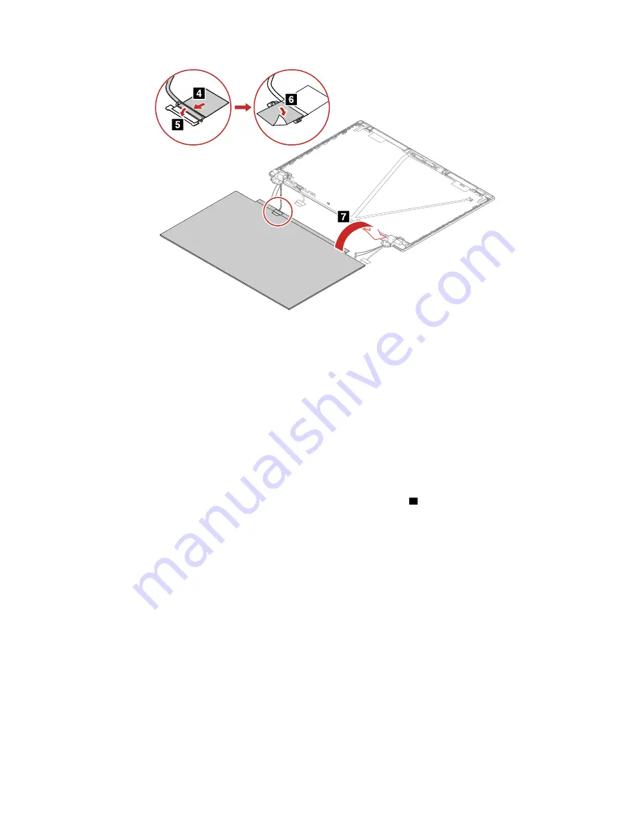
Removal and installation steps of the LCD panel and the LCD elastic adhesive tapes (for computer
models with the aluminum LCD cover assembly and E-privacy touch panel)
Removal steps of the LCD panel and the LCD elastic adhesive tapes
1. Grasp the end of elastic adhesive tapes with tweezers. Pull out each tape slowly in the direction as
shown until three elastic adhesive tapes are all released from LCD unit
1
.
Note:
Do not pull the tapes too fast, otherwise, the tapes might snap.
108
T14 Gen 2 and P14s Gen 2 Hardware Maintenance Manual
Содержание ThinkPad P14s Gen 1
Страница 1: ...T14 Gen 2 and P14s Gen 2 Hardware Maintenance Manual ...
Страница 6: ...iv T14 Gen 2 and P14s Gen 2 Hardware Maintenance Manual ...
Страница 11: ...DANGER DANGER DANGER DANGER DANGER DANGER Chapter 1 Safety information 5 ...
Страница 12: ...DANGER 6 T14 Gen 2 and P14s Gen 2 Hardware Maintenance Manual ...
Страница 13: ...PERIGO Chapter 1 Safety information 7 ...
Страница 14: ...PERIGO PERIGO PERIGO PERIGO 8 T14 Gen 2 and P14s Gen 2 Hardware Maintenance Manual ...
Страница 15: ...PERIGO PERIGO PERIGO DANGER DANGER Chapter 1 Safety information 9 ...
Страница 16: ...DANGER DANGER DANGER DANGER DANGER 10 T14 Gen 2 and P14s Gen 2 Hardware Maintenance Manual ...
Страница 17: ...DANGER VORSICHT VORSICHT VORSICHT VORSICHT Chapter 1 Safety information 11 ...
Страница 18: ...VORSICHT VORSICHT VORSICHT VORSICHT 12 T14 Gen 2 and P14s Gen 2 Hardware Maintenance Manual ...
Страница 19: ...Chapter 1 Safety information 13 ...
Страница 20: ...14 T14 Gen 2 and P14s Gen 2 Hardware Maintenance Manual ...
Страница 21: ...Chapter 1 Safety information 15 ...
Страница 22: ...16 T14 Gen 2 and P14s Gen 2 Hardware Maintenance Manual ...
Страница 23: ...Chapter 1 Safety information 17 ...
Страница 24: ...18 T14 Gen 2 and P14s Gen 2 Hardware Maintenance Manual ...
Страница 25: ...Chapter 1 Safety information 19 ...
Страница 26: ...20 T14 Gen 2 and P14s Gen 2 Hardware Maintenance Manual ...
Страница 30: ...24 T14 Gen 2 and P14s Gen 2 Hardware Maintenance Manual ...
Страница 48: ...42 T14 Gen 2 and P14s Gen 2 Hardware Maintenance Manual ...
Страница 75: ...a b c d Chapter 8 Removing or replacing a FRU 69 ...
Страница 102: ...96 T14 Gen 2 and P14s Gen 2 Hardware Maintenance Manual ...
Страница 105: ...Removal steps of the LCD unit for Intel models Chapter 8 Removing or replacing a FRU 99 ...
Страница 133: ......
Страница 134: ...Part Number SP40W87698_01 Printed in China 1P P N SP40W87698_01 ...
Страница 135: ... 1PSP40W87698_01 ...


