background image

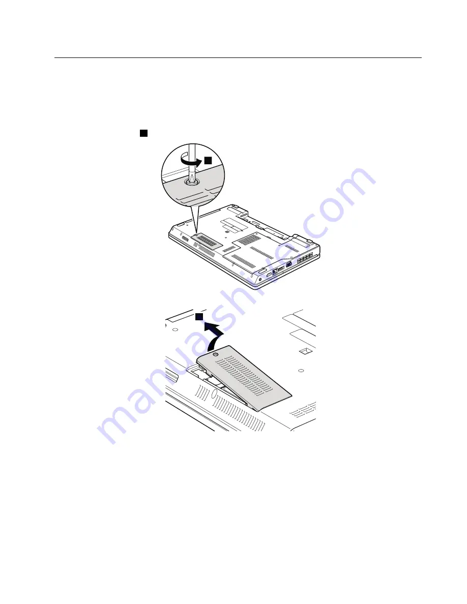
1080 Wireless WAN slot cover and PCI Express Mini Card for wireless
WAN

For access, remove this FRU:

“1010 Battery pack” on page 58

Table 15. Removal steps of wireless WAN slot cover and PCI Express Mini Card for wireless WAN

Note:

Loosen the screw

1

, but do

not

remove it.

1

2

Chapter 8

.

Removing or replacing a FRU

67

Содержание ThinkPad Edge 15

Страница 1: ...Hardware Maintenance Manual ThinkPad Edge 14 Edge 15 E40 and E50 ...

Страница 2: ...Notices on page 149 Fifth Edition April 2012 Copyright Lenovo 2010 2012 LIMITED AND RESTRICTED RIGHTS NOTICE If products data computer software and services are delivered pursuant a General Services Administration GSA contract use reproduction or disclosure is subject to restrictions set forth in Contract No GS 35F 05925 ...

Страница 3: ...g the factory contents by using Recovery Disc Set 39 Passwords 40 Power on password 40 Hard disk password 40 Supervisor password 41 How to remove the power on password 41 How to remove the hard disk password 41 Power management 42 Screen blank mode 42 Sleep mode 42 Hibernation mode 42 Symptom to FRU index 43 Numeric error codes 43 Error messages 45 No beep symptoms 46 LCD related symptoms 46 Inter...

Страница 4: ... 9 Locations 101 Front view 101 Rear view 102 Bottom view 103 Chapter 10 Parts list 105 Overall 106 LCD FRUs 123 Keyboard 138 Miscellaneous parts 140 AC adapters 140 Power cords 141 Recovery discs 142 Windows 7 Home Basic 32 bit DVDs 142 Windows 7 Home Premium 32 bit DVDs 142 Windows 7 Home Premium 64 bit DVDs 143 Windows 7 Professional 32 bit DVDs 144 Windows 7 Professional 64 bit DVDs 145 Common...

Страница 5: ... advanced diagnostic tests to troubleshoot problems Important This manual is intended only for trained service technicians who are familiar with ThinkPad products Use this manual along with the advanced diagnostic tests to troubleshoot problems effectively Before servicing a ThinkPad product be sure to read all the information underChapter 1 Safety information on page 1 and Chapter 2 Important ser...

Страница 6: ...iv Hardware Maintenance Manual ...

Страница 7: ...unsafe Before you start the machine make sure that other service technicians and the customer s personnel are not in a hazardous position Place removed covers and other parts in a safe place away from all personnel while you are servicing the machine Keep your toolcase away from walk areas so that other people will not trip over it Do not wear loose clothing that can be trapped in the moving parts...

Страница 8: ...n working with powered on electrical equipment keep the other hand in your pocket or behind your back Attention An electrical shock can occur only when there is a complete circuit By observing the above rule you may prevent a current from passing through your body When using testers set the controls correctly and use the approved probe leads and accessories for that tester Stand on suitable rubber...

Страница 9: ...task Begin the checks with the power off and the power cord disconnected Checklist 1 Check exterior covers for damage loose broken or sharp edges 2 Power off the computer Disconnect the power cord 3 Check the power cord for a A third wire ground connector in good condition Use a meter to measure third wire ground continuity for 0 1 ohm or less between the external ground pin and the frame ground b...

Страница 10: ...provide protection that meets the specific service requirement Note The use of a grounding system to guard against ESD damage is desirable but not necessary Attach the ESD ground clip to any frame ground ground braid or green wire ground When working on a double insulated or battery operated system use an ESD common ground or reference point You can use coax or connector outside shells on these sy...

Страница 11: ...DANGER DANGER DANGER DANGER DANGER DANGER Chapter 1 Safety information 5 ...

Страница 12: ...DANGER 6 Hardware Maintenance Manual ...

Страница 13: ...PERIGO PERIGO PERIGO Chapter 1 Safety information 7 ...

Страница 14: ...PERIGO PERIGO PERIGO PERIGO PERIGO 8 Hardware Maintenance Manual ...

Страница 15: ...DANGER DANGER DANGER DANGER DANGER Chapter 1 Safety information 9 ...

Страница 16: ...DANGER DANGER DANGER VORSICHT VORSICHT 10 Hardware Maintenance Manual ...

Страница 17: ...VORSICHT VORSICHT VORSICHT VORSICHT VORSICHT VORSICHT Chapter 1 Safety information 11 ...

Страница 18: ...12 Hardware Maintenance Manual ...

Страница 19: ...Chapter 1 Safety information 13 ...

Страница 20: ...14 Hardware Maintenance Manual ...

Страница 21: ...Chapter 1 Safety information 15 ...

Страница 22: ...16 Hardware Maintenance Manual ...

Страница 23: ...ual translations The laser compliance statements in this section are provided in the following languages English Arabic Brazilian Portuguese French German Hebrew Japanese Korean Spanish Traditional Chinese Chapter 1 Safety information 17 ...

Страница 24: ...18 Hardware Maintenance Manual ...

Страница 25: ...Chapter 1 Safety information 19 ...

Страница 26: ...20 Hardware Maintenance Manual ...

Страница 27: ...Chapter 1 Safety information 21 ...

Страница 28: ...22 Hardware Maintenance Manual ...

Страница 29: ...es drivers and BIOS downloads are installed before replacing any FRUs listed in this manual After a system board is replaced ensure that the latest BIOS is loaded to the system board before completing the service action To download software fixes drivers and BIOS do as follows 1 Go to http support lenovo com 2 Enter the product number of the computer or press Auto detect button on the screen 3 Sel...

Страница 30: ...d on the screen to diagnose failures If more than one error code is displayed begin the diagnosis with the first error code Whatever causes the first error code may also cause false error codes If no error code is displayed see whether the error symptom is listed in the Symptom to FRU Index for the computer you are servicing Strategy for replacing FRUs for CTO CMV and GAV Product definition Dynami...

Страница 31: ...ample 1829 F1U PEW can be accessed at the following Web site http www lenovo com support site wss document do lndocid LOOK WARNTY Select Warranty lookup Input the MT and the Serial number and the list of key commodities will be returned in the PEW record under COMPONENT INFORMATION Using eSupport For key commodities examples hard disk drive system board microprocessor LCD and memory eSupport can b...

Страница 32: ...Use the HMM as a backup to PEW and eSupport to view the complete list of FRUs at the MT model level 26 Hardware Maintenance Manual ...

Страница 33: ... and the FRU part number are correct by referring to the FRU parts list A FRU should not be replaced because of a single unreproducible failure Single failures can occur for a variety of reasons that have nothing to do with a hardware defect such as cosmic radiation electrostatic discharge or software errors Consider replacing a FRU only when a problem recurs If you suspect that a FRU is defective...

Страница 34: ... by nonwarranted activities Missing parts might be a symptom of unauthorized service or modification If the spindle of a hard disk drive becomes noisy it may have been subjected to excessive force or dropped Checkout guide Use the following procedures as a guide in identifying and correcting problems with the ThinkPad Notebook Note The diagnostic tests are intended to test only ThinkPad products T...

Страница 35: ...testing of the device Using a bootable PC Doctor for DOS CD DVD the system can be started from a USB attached optical drive To run the test do as follows 1 Turn off the computer 2 Make sure that the optical drive that is supported as a startup device is installed to the computer you are servicing 3 Turn on the computer If the computer cannot be powered on go to Power system checkout on page 35 and...

Страница 36: ... Signature Chip the security chip must be set to Active 10 Run the applicable function test 11 Follow the instructions on the screen If there is a problem PC Doctor shows messages describing it 12 To exit the test select Quit Exit Diag To cancel the test press Esc Note After running PC Doctor check the time and date on the system and reset them if they are incorrect Detecting system information wi...

Страница 37: ...f the computer without starting up the operating system To run the test do as follows 1 Power off the computer and then power it on again 2 When the ThinkPad logo comes up immediately press Enter key The Rescue and Recovery workspace opens 3 Click Launch advanced Rescue and Recovery 4 Click Diagnose hardware For more information about PC Doctor see the Help for the program Lenovo Solution Center T...

Страница 38: ... do the following 1 Turn on the computer If the computer cannot be turned on go to Power system checkout on page 35 and check the power sources If an error code is displayed go to Symptom to FRU index on page 43 for error code descriptions and troubleshooting hints 2 When the ThinkPad logo is displayed repeatedly press and release the F12 key When the Boot Menu window opens release the F12 key 3 P...

Страница 39: ...to FRU index on page 43 for error code descriptions and troubleshooting hints 2 Insert the CD into the optical drive 3 Restart the computer 4 When the ThinkPad logo is displayed repeatedly press and release the F12 key When the Boot Menu window opens release the F12 key 5 Use the arrow keys to select ATAPI CDx x 0 1 and then press Enter The diagnostic program will be launched automatically 6 Follo...

Страница 40: ...nter is displayed at the lower left of the screen press F1 to enter the BIOS Setup Utility 4 Using cursor keys select HDD diagnostic program Press enter 5 Using cursor keys select Main hard disk drive 6 Press Enter to start the diagnostic program Diskette drive 1 Diagnostics Diskette Drives 2 Interactive Tests Diskette Memory 1 If two DIMMs are installed remove one of them and run Diagnostics Adva...

Страница 41: ...ional charging on page 35 To check the ac adapter do the following 1 Unplug the ac adapter cable from the computer 2 Measure the output voltage at the plug of the ac adapter cable See the following figure Pin Voltage V dc 1 20 2 0 3 Ground 1 2 3 20V Note Output voltage of pin no 2 of the ac adapter may different from the one you are servicing 3 If the voltage is not correct replace the ac adapter ...

Страница 42: ...r it cools down reinstall and recharge it To check the battery pack do the following 1 Power off the computer 2 Remove the battery pack and measure the voltage between battery terminals 1 and 7 See the following figure Terminal Voltage V dc 1 0 to 12 6 7 Ground 1 2 3 4 5 6 7 3 If the voltage is less than 11 0 V dc the battery pack has been discharged Note Recharging will take at least 3 hours even...

Страница 43: ...Black Ground If the voltage is correct replace the system board If the voltage is not correct replace the backup battery If the backup battery discharges quickly after replacement replace the system board Chapter 3 General checkout 37 ...

Страница 44: ...38 Hardware Maintenance Manual ...

Страница 45: ...covery Disc one or more discs This disc restores the preinstalled applications and drivers on the computer Supplemental Recovery Disc This disc contains additional content such as updates to the software that was preinstalled on the computer Not all recovery disc sets come with a Supplemental Recovery Disc Notes You must have a DVD drive to use the recovery discs If you do not have an internal DVD...

Страница 46: ...11 After you have completed the Windows setup you might want to restore the original startup sequence Start the Setup Utility program and then press F9 to restore the default settings Press F10 to save and exit the Setup Utility Note After restoring a drive to the factory default settings you might need to reinstall some device drivers Passwords As many as three passwords may be needed for any Thi...

Страница 47: ...s After the POST ends the password prompt does not appear The POP has been removed 5 Reinstall the backup battery and the battery pack B If an SVP has been set and is known by the service technician 1 Turn on the computer 2 When the ThinkPad logo comes up immediately press F1 to enter BIOS Setup Utility For models supporting the Passphrase function press F1 while the POP icon is appearing on the s...

Страница 48: ...and press Enter twice 8 Press F10 9 Select Yes in the Setup Configuration window Both user HDP and master HDP will have been removed Power management To reduce power consumption the computer has three power management modes screen blank sleep and hibernation Screen blank mode To put the computer into screen blank mode do as follows 1 Right click the Power Manager Battery Gauge in the task bar 2 Se...

Страница 49: ... FRUs are likely to need to be replaced next A numeric error is displayed for each error detected in POST or system operation In the displays n can be any number If no numeric code is displayed check the narrative descriptions of symptoms If the symptom is not described there go to Intermittent problems on page 46 Note For a device not supported by diagnostic codes in the ThinkPad Notebooks see th...

Страница 50: ...up Utility to reset the time and date 0254 System NV7 Volume checksum bad Default configuration used two short beeps Turn off the computer and discharge CMOS Then restart the computer 0260 System timer error two short beeps 1 Charge the backup battery for more than 8 hours by connecting the ac adapter 2 Replace the backup battery and run BIOS Setup Utility to reset the time and date 3 System board...

Страница 51: ...setting by pressing F10 and restart the computer Fan error four short beeps one long beep 1 Fan 2 Thermal grease 3 System board DRAM is unplugged one short beep pause three short beeps pause three short beeps pause one short beep Memory card is not installed Install memory card DRAM is not well plugged one short beep pause three short beeps pause three short beeps pause one short beep Reinstall th...

Страница 52: ...t will be deemed as defective by Lenovo and it should be replaced Notes This policy applies to all ThinkPad Notebooks purchased on 1 January 2008 or later Lenovo will not provide replacement if the LCD is within specification as we cannot guarantee that any replacement LCD will have zero pixel defects One pixel consists of R G B sub pixels Table 5 LCD related symptoms Symptom or error FRU or actio...

Страница 53: ...ter Verify that the power supply being used at the time of the failure is operating correctly See Power system checkout on page 35 1 Turn off the computer 2 Visually check each FRU for damage Replace any damaged FRU 3 Remove or disconnect all of the following devices a Non ThinkPad devices b Printer mouse and other external devices c Battery pack d Hard disk drive e External diskette drive or opti...

Страница 54: ...48 Hardware Maintenance Manual ...

Страница 55: ...harged when this indicator is on Off The ac adapter is not connected Sleep standby status 2 Sleep standby status The illumination dot in the ThinkPad logo on the outer lid of the computer and on the palm rest works as a system status indicator it shows whether the computer is in sleep standby hibernation or normal model Red The computer is on in normal mode Fast blinking red The computer is enteri...

Страница 56: ... or in hibernation mode On screen indicators Caps lock Caps Lock mode is enabled You can enter all alphabetic characters A Z in uppercase without pressing the Shift key Wireless status Press F9 to enable or disable the wireless features You can quickly change the power state of each feature in the list 50 Hardware Maintenance Manual ...

Страница 57: ... are set on mute or unmute this is the default setting Camera mute F5 During a video conference you can control the video streaming from the integrated camera by pressing this key The video output will be grayed out and the audio streaming will continue Switching a display output location F6 For Windows 7 Switch between the computer display and an external monitor Windows will show these display o...

Страница 58: ...you press this key a list of wireless features is displayed You can quickly change the power state of each feature in the list Notes To use this function following device drivers must be installed on the computer beforehand Power Management driver OnScreen Display Utility Wireless device drivers Fn Spacebar some models Some models have a backlit keyboard To illuminate the keyboard in less than per...

Страница 59: ...y be charged for the replacement CRU if Lenovo does not receive the defective part within thirty 30 days of your receipt of the replacement CRU See your Lenovo Limited Warranty documentation for full details This chapter presents notices related to removing and replacing parts Read this chapter carefully before replacing any FRU Screw notices Loose screws can cause a reliability problem In the Thi...

Страница 60: ...u must restore the serial number of the system unit to its original value Before replacing the system board save the original serial number by doing the following 1 Install the LENOVO ThinkPad Hardware Maintenance Diskette Version 1 76 or later and restart the computer 2 From the main menu select 1 Set System Identification 3 Select 2 Read S N data from EEPROM The serial number of each device in y...

Страница 61: ...e ECA Information Read Write function on the LENOVO ThinkPad Hardware Maintenance Diskette Version 1 76 or later 1 Insert the LENOVO ThinkPad Hardware Maintenance Diskette Version 1 76 or later and restart the computer 2 From the main menu select 6 Set ECA Information 3 To read ECA information select 2 Read ECA rework number from EEPROM and follow the instruction 4 To read box build date select 5 ...

Страница 62: ...56 Hardware Maintenance Manual ...

Страница 63: ...runs the risk of damaging parts 2 Before replacing any FRU review Chapter 7 FRU replacement notices on page 53 3 Begin by removing any FRUs that have to be removed before the failing FRU Any such FRUs are listed at the top of the page Remove them in the order in which they are listed 4 Follow the correct sequence in the steps for removing the FRU as given in the drawings by the numbers in square c...

Страница 64: ...a non physically damaged battery pack is replaced Note that the replacement of a physically damaged battery pack is not covered by the warranty Table 8 Removal steps of battery pack DANGER Use only the battery specified in the parts list for your computer Any other battery could ignite or explode Unlock the battery latch 1 Holding the battery lock lever in the unlocked position 2 remove the batter...

Страница 65: ...ive or travel cover 1 Step Screw quantity Color Torque 1 M2 8 mm wafer head nylon coated 1 Black 0 181 Nm 1 85 kgfcm 3 2 1030 Thermal cover For access remove this FRU 1010 Battery pack on page 58 Chapter 8 Removing or replacing a FRU 59 ...

Страница 66: ...DD assembly For access remove these FRUs in order 1010 Battery pack on page 58 1030 Thermal cover on page 59 Attention Do not drop the drive or apply any physical shock to it The drive is sensitive to physical shock Improper handling can cause damage and permanent loss of data Before removing the drive have the user make a backup copy of all the information on it if possible Never remove the drive...

Страница 67: ...connector is attached firmly 2 a When installing Do not apply excessive force to the HDD bracket a To do so you might bend or break it 1050 DIMM For access remove these FRUs in order 1010 Battery pack on page 58 1030 Thermal cover on page 59 Chapter 8 Removing or replacing a FRU 61 ...

Страница 68: ... must be installed in SLOT 0 a lower slot but not in SLOT 1 b upper slot 2 a When installing Insert the notched end of the DIMM into the socket Press the DIMM firmly and pivot it until it snaps into the place Make sure that it is firmly fixed in the slot and does not move easily 62 Hardware Maintenance Manual ...

Страница 69: ...onents Do not touch or apply any excessive force to the fan motor It might cause damage to the fan assembly or the computer to mulfunction Table 13 Removal steps of fan assembly 1 When installing Make sure that the fan connector is attached firmly to the system board Note Loosen the screws 2a to 2f in order but do not remove them When you attach the fan secure the screws in order For Thinkpad Edge...

Страница 70: ...2c 2a 2d 2f 2e For ThinkPad Edge 14 and E40 2b 2c 2a 2d Note Step 3 is only for ThinkPad Edge 15 For ThinkPad Edge 14 skip step 3 Step Screw quantity Color Torque 3 M2 4 mm wafer head nylon coated 1 Silver 0 181 Nm 1 85 kgfcm 64 Hardware Maintenance Manual ...

Страница 71: ... the parts marked a as in the following figures Either too much or too less application of grease can cause a thermal problem due to imperfect contact with a component For the new CPU thermal device fan you need to peel the thin film off from the rubbers marked b For discrete fan assembly b b a a a For integrated fan assembly Chapter 8 Removing or replacing a FRU 65 ...

Страница 72: ...ion CPU is extremely sensitive When you service the CPU avoid any kind of rough handling Table 14 Removal steps of CPU Rotate the head of the screw in the direction shown by arrow 1 to release the lock then remove the CPU 2 1 2 a When installing Place the CPU on the CPU socket and then rotate the head of the screw in the direction shown by arrow a to secure the CPU 66 Hardware Maintenance Manual ...

Страница 73: ... for wireless WAN For access remove this FRU 1010 Battery pack on page 58 Table 15 Removal steps of wireless WAN slot cover and PCI Express Mini Card for wireless WAN Note Loosen the screw 1 but do not remove it 1 2 Chapter 8 Removing or replacing a FRU 67 ...

Страница 74: ...to the jack labeled MAIN and the blue cable 3b into the jack labeled AUX on the card Step Screw quantity Color Torque 4 M2 3 mm wafer head nylon coated 2 Black 0 181 Nm 1 85 kgfcm 5 Table 16 Removal steps of SIM card Some models of ThinkPad Edge 14 Edge 15 E40 and E50 might have the SIM card that the customer has been installed If you need to replace the system board in those models remove the SIM...

Страница 75: ...e 58 1020 Optical drive or travel cover on page 58 Note In models with the fingerprint reader the sensor is attached to the palm rest FRU If the fingerprint reader has any defects you can replace it by the procedures given in this section which are the same for a palm rest with or without a fingerprint reader Chapter 8 Removing or replacing a FRU 69 ...

Страница 76: ... 1 1 1 2 2 Step Screw quantity Color Torque 1 M2 8 mm wafer head nylon coated 5 Black 0 181 Nm 1 85 kgfcm 1a M2 5 mm wafer head nylon coated 1 Black 0 181 Nm 1 85 kgfcm 2 M2 3 mm wafer head nylon coated 1 Black 0 181 Nm 1 85 kgfcm 3 3 4 70 Hardware Maintenance Manual ...

Страница 77: ...ation of palm rest assembly with cables When installing 1 Attach the cables to the system board firmly 2 Attach the palm rest so that the two small projections of the palm rest firmly fit into the guide holes of the keyboard bezel as shown in this figure Chapter 8 Removing or replacing a FRU 71 ...

Страница 78: ...til it clicks into place 4 Close the LCD cover and turn the computer over Then fasten the screws to secure the palm rest 1100 PCI Express Mini Card for wireless LAN For access remove these FRUs in order 1010 Battery pack on page 58 1020 Optical drive or travel cover on page 58 72 Hardware Maintenance Manual ...

Страница 79: ...1a and 1b unplug the jacks by using the removal tool antenna RF connector P N 08K7159 or pick the connectors with your fingers and gently unplug them in direction of the arrow 2 2 1a 1b Step Screw quantity Color Torque 2 M2 3 mm wafer head nylon coated 2 Black 0 181 Nm 1 85 kgfcm 3 Chapter 8 Removing or replacing a FRU 73 ...

Страница 80: ...ss remove these FRUs in order 1010 Battery pack on page 58 1020 Optical drive or travel cover on page 58 1090 Palm rest assembly with cables on page 69 DANGER Use only the battery specified in the parts list for your computer Any other battery could ignite or explode Table 20 Removal steps of backup battery 2 1 When installing Make sure that the battery connector is attached firmly to the system b...

Страница 81: ...2 2 1 Step Screw quantity Color Torque 1 M2 3 mm wafer head nylon coated 1 Black 0 181 Nm 1 85 kgfcm When installing Make sure that the connector on bottom side of the card is attached firmly to the system board 1130 Keyboard For access remove these FRUs in order 1010 Battery pack on page 58 1020 Optical drive or travel cover on page 58 1090 Palm rest assembly with cables on page 69 Chapter 8 Remo...

Страница 82: ... 1 1 Step Screw quantity Color Torque 1 M2 5 mm wafer head nylon coated 1 Black 0 181 Nm 1 85 kgfcm 2 2 4 5 3 Step Screw quantity Color Torque 6 M2 3 mm wafer head nylon coated 1 Black 0 181 Nm 1 85 kgfcm 76 Hardware Maintenance Manual ...

Страница 83: ...d 1 Attach the connectors 2 Attach the keyboard so that the keyboard edges are under the frame as shown in this figure 3 To make sure that the front side of the keyboard is housed firmly gently press the keys with your thumbs and try to slide the keyboard toward you 4 Secure the keyboard by tightening the screws from the bottom side of the computer Chapter 8 Removing or replacing a FRU 77 ...

Страница 84: ...n page 58 1090 Palm rest assembly with cables on page 69 1130 Keyboard on page 75 Table 24 Removal steps of keyboard bezel 1 2 2 2 2 2 1 Step Screw quantity Color Torque 1 M2 5 6 5 mm wafer head nylon coated 2 Black 0 392 Nm 4 kgfcm 2 M2 3 mm wafer head nylon coated 5 Black 0 181 Nm 1 85 kgfcm 78 Hardware Maintenance Manual ...

Страница 85: ... continued 4 5 6 3 3 Step Screw quantity Color Torque 3 M2 3 mm wafer head nylon coated 2 Black 0 181 Nm 1 85 kgfcm When installing Make sure that the connectors are attached firmly to the system board Chapter 8 Removing or replacing a FRU 79 ...

Страница 86: ...vel cover on page 58 1080 Wireless WAN slot cover and PCI Express Mini Card for wireless WAN on page 67 1090 Palm rest assembly with cables on page 69 1100 PCI Express Mini Card for wireless LAN on page 72 1130 Keyboard on page 75 1140 Keyboard bezel on page 78 Table 25 Removal steps of LCD unit 1 1 Step Screw quantity Color Torque 80 Hardware Maintenance Manual ...

Страница 87: ...em board In step 4 release wireless antenna cables from the cable guides 4 4 4 4 4 4 4 4 4 4 4 When installing Make sure that the cables are attached to the cable guides firmly Attention When you route the cables make sure that they are not subjected to any tension Tension could cause the cables to be damaged by the cable guides or a wire to be broken Chapter 8 Removing or replacing a FRU 81 ...

Страница 88: ...Steps 5a are for ThinkPad Edge 14 and E40 and steps 5b are for ThinkPad Edge 15 and E50 5b 5b 5a 5a 5b 5b 5a 5a Step Screw quantity Color Torque 5a or 5b M2 5 6 5 mm wafter head nylon coated 4 Black 0 392 Nm 4 kgfcm 82 Hardware Maintenance Manual ...

Страница 89: ... 58 1080 Wireless WAN slot cover and PCI Express Mini Card for wireless WAN on page 67 1090 Palm rest assembly with cables on page 69 1100 PCI Express Mini Card for wireless LAN on page 72 1130 Keyboard on page 75 1140 Keyboard bezel on page 78 1150 LCD unit on page 80 Table 26 Removal steps of top shielding assembly For ThinkPad Edge 15 and E50 Chapter 8 Removing or replacing a FRU 83 ...

Страница 90: ... Torque 1 M2 2 mm wafer head nylon coated 3 Silver 0 181 Nm 1 85 kgfcm 2 M2 3 mm wafer head nylon coated 5 Black 0 181 Nm 1 85 kgfcm 3 M2 5 mm wafer head nylon coated 2 Black 0 181 Nm 1 85 kgfcm For ThinkPad Edge 14 and E40 1 2 2 3 3 3 3 4 Step Screw quantity Color Torque 84 Hardware Maintenance Manual ...

Страница 91: ...ect report and replace the system board Avoid rough handling of any kind At every point in the process be sure not to drop or stack the system board If you put a system board down be sure to put it only on a padded surface such as an ESD mat or conductive corrugated material After replacing the system board run PC Doctor for DOS to make sure that HDD Active Protection System still functions The pr...

Страница 92: ...d on the top side of the system board are extremely sensitive When you service the system board avoid any kind of rough handling a GMCH Integrated video chip b CPU c ICH I O Controller Hub d Video chip only for discrete models For ThinkPad Edge 14 and E40 integrated models a b c For ThinkPad Edge 14 and E40 discrete models c d a b 86 Hardware Maintenance Manual ...

Страница 93: ...ntinued For ThinkPad Edge 15 and E50 integrated models a b c For ThinkPad Edge 15 and E50 discrete models c d a b Table 28 Removal steps of system board assembly For ThinkPad Edge 15 and E50 1 1 1 1 Step Screw quantity Color Torque Chapter 8 Removing or replacing a FRU 87 ...

Страница 94: ...p Screw quantity Color Torque 1 M2 5 mm wafer head nylon coated 2 Black 0 181 Nm 1 85 kgfcm 2 3 When installing Make sure that the connectors are attached firmly to the system board 1180 USB connector board and USB cable assembly For access remove these FRUs in order 1010 Battery pack on page 58 1030 Thermal cover on page 59 88 Hardware Maintenance Manual ...

Страница 95: ...n page 78 1150 LCD unit on page 80 1160 Top shielding assembly on page 83 Table 29 Removal steps of USB connector board and USB cable assembly 3 2 4 1 When installing Make sure that the connectors are attached firmly Step Screw quantity Color Torque 2 M2 3 mm wafer head nylon coated 1 Black 0 181 Nm 1 85 kgfcm Cable routing Route the USB cable assembly as shown in these figures For ThinkPad Edge 1...

Страница 96: ...070 CPU on page 66 1080 Wireless WAN slot cover and PCI Express Mini Card for wireless WAN on page 67 1090 Palm rest assembly with cables on page 69 1100 PCI Express Mini Card for wireless LAN on page 72 1110 Backup battery on page 74 1120 Bluetooth daughter card BDC 2 on page 75 1130 Keyboard on page 75 1140 Keyboard bezel on page 78 1150 LCD unit on page 80 1160 Top shielding assembly on page 83...

Страница 97: ... 4 Step Screw quantity Color Torque 1 M2 3 mm wafer head nylon coated 2 Black 0 181 Nm 1 85 kgfcm For ThinkPad Edge 14 and E40 1 2 3 4 Step Screw quantity Color Torque 1 M2 5 mm wafer head nylon coated 1 Black 0 181 Nm 1 85 kgfcm Chapter 8 Removing or replacing a FRU 91 ...

Страница 98: ...3 is attached to a part that is replaced return the old part with the label attached to the customer or provide a letter to the customer stating what the label was originally on the system and what the label part number serial number and product key were When you replace the base cover apply the following labels 4 Battery word label 6 Homologation label The following labels need to be peeled off f...

Страница 99: ...or some models you also need to apply one or two FCC labels Check the old base cover if it has one or two FCC labels find duplicates of them in the label kit and apply them to the new base cover For the location of each label refer to the following figures For ThinkPad Edge 15 and E50 2 3 8 9 4 1 5 6 7 10 12 11 Chapter 8 Removing or replacing a FRU 93 ...

Страница 100: ...d for wireless WAN on page 67 1090 Palm rest assembly with cables on page 69 1100 PCI Express Mini Card for wireless LAN on page 72 1130 Keyboard on page 75 1140 Keyboard bezel on page 78 1150 LCD unit on page 80 Table 31 Removal steps of LCD front bezel 1 1 1 1 Step Screw cap Screw quantity Color Torque 1 M2 5 mm wafer head nylon coated 4 Black 0 181 Nm 1 85 kgfcm 94 Hardware Maintenance Manual ...

Страница 101: ...in order 1010 Battery pack on page 58 1080 Wireless WAN slot cover and PCI Express Mini Card for wireless WAN on page 67 1090 Palm rest assembly with cables on page 69 1100 PCI Express Mini Card for wireless LAN on page 72 1130 Keyboard on page 75 1140 Keyboard bezel on page 78 1150 LCD unit on page 80 2010 LCD front bezel on page 94 Table 32 Removal steps of speaker assembly 1 1 2 3 Chapter 8 Rem...

Страница 102: ...0 Keyboard bezel on page 78 1150 LCD unit on page 80 2010 LCD front bezel on page 94 Table 33 Removal steps of integrated camera 1 2 When installing Make sure that the connector is attached firmly 2040 Hinges LCD panel LCD cable and LCD rear cover assembly For access remove these FRUs in order 1010 Battery pack on page 58 1080 Wireless WAN slot cover and PCI Express Mini Card for wireless WAN on p...

Страница 103: ...Edge 15 and E50 1 1 1 1 2 2 2 2 Step Screw quantity Color Torque 1 M2 5 mm wafer head nylon coated 4 Black 0 181 Nm 1 85 kgfcm For ThinkPad Edge 14 and E40 1 1 Step Screw quantity Color Torque 1 M2 5 mm wafer head nylon coated 2 Black 0 181 Nm 1 85 kgfcm Chapter 8 Removing or replacing a FRU 97 ...

Страница 104: ...Table 34 Removal steps of hinges LCD panel LCD cable and LCD rear cover assembly continued 3 4 5 6 7 98 Hardware Maintenance Manual ...

Страница 105: ...s in order 1010 Battery pack on page 58 1080 Wireless WAN slot cover and PCI Express Mini Card for wireless WAN on page 67 1090 Palm rest assembly with cables on page 69 1100 PCI Express Mini Card for wireless LAN on page 72 1130 Keyboard on page 75 1140 Keyboard bezel on page 78 1150 LCD unit on page 80 2010 LCD front bezel on page 94 2020 Speaker assembly on page 95 2030 Integrated camera on pag...

Страница 106: ...cover assembly and from the hinges 1 2 2 1 1 1 1 1 1 1 When installing Route the cables as shown in this figure When you route the cables make sure that they are not subjected to any tension Tension could cause the cables to be damaged by the cable guides or a wire to be broken 100 Hardware Maintenance Manual ...

Страница 107: ...ote For the description of the indicator see Chapter 5 Status indicators on page 49 7 AC power connector 8 Optical drive or travel cover 9 Universal serial bus USB connectors 10 Sleep standby status indicator Note For the description of the indicator see Chapter 5 Status indicators on page 49 11 Fingerprint reader for some models 12 Touch pad buttons 13 Touch pad 14 TrackPoint buttons 15 TrackPoin...

Страница 108: ...standby status indicator Note For the description of the indicator see Chapter 5 Status indicators on page 49 2 Combo audio jack 3 HDMI port 4 RJ 45 Ethernet connector 5 eSATA USB connector 6 External monitor connector 3 4 5 6 2 1 102 Hardware Maintenance Manual ...

Страница 109: ...Bottom view 1 Battery pack 2 Battery pack latch 3 Thermal slot DIMM hard disk drive fan assembly 4 Wireless WAN card slot 5 Media Card Reader 1 2 3 4 5 Chapter 9 Locations 103 ...

Страница 110: ...104 Hardware Maintenance Manual ...

Страница 111: ...bility you may request that Lenovo installs an Optional service CRU according to the warranty service for your product Where you are installing the CRU Lenovo will ship the CRU to you CRU information and replacement instructions are shipped with your product and are available from Lenovo at any time upon request You may find a list of CRUs in the publications that ship with your product or at http...

Страница 112: ...Overall 1 5 3 2 4 6 7 9 10 11 12 13 16 14 15 17 20 21 19 18 22 8 106 Hardware Maintenance Manual ...

Страница 113: ...x 47x 46x 45x 44x 43x 42x 3Zx 3Yx 3Xx 3Wx 3Vx 3Ux 3Tx 3Sx 3Rx 3Qx 3Px 55Y3713 4 1 GB DDR3 1333 SDRAM SO DIMM PC3 10600 card 0199 CTO 6Px 6Qx 0301 all 0302 CTO 54x 55x 0319 CTO 0578 all 0579 CTO 55Y3715 4 2 GB DDR3 1333 SDRAM SO DIMM PC3 10600 card 0199 CTO 6Px 6Qx 0301 all 0302 CTO 54x 55x 0319 CTO 0578 CTO all 0579 CTO 55Y3716 4 4 GB DDR3 1333 SDRAM SO DIMM PC3 10600 card 0199 CTO 0301 CTO CSx CU...

Страница 114: ...x 4Jx 4Kx 0301 CTO 23x 24x 26x 27x 28x 29x 2Ax 2Bx 2Cx 2Dx 2Fx 2Gx 2Hx 2Jx 2Kx 2Lx 2Mx 2Nx 2Px 2Qx 2Rx 2Sx 2Tx 2Ux 2Vx 2Wx 2Xx 2Yx 2Zx 33x 34x 35x 36x 37x 38x 39x 3Ax 3Bx 0302 CTO 22x 23x 25x 26x 27x 2Ax 2Bx 2Cx 2Dx 2Ex 2Fx 2Gx 2Hx 2Jx 2Kx 2Lx 2Mx 2Nx 2Px 2Qx 2Rx 2Sx 2Tx 2Ux 2Vx 2Wx 2Xx 2Yx 2Zx 33x 34x 36x 37x 38x 39x 3Ax 3Bx 3Ex 0319 CTO 49x 48x 47x 46x 45x 44x 43x 42x 3Zx 3Yx 3Vx 3Ux 3Tx 3Sx 3Rx...

Страница 115: ...Gx 5Hx 5Jx 5Lx RZx 5Sx 68x 69x 6Ax 0301 CTO 24x 25x 26x 28x 29x 2Ax 2Bx 2Cx 2Ex 2Hx 2Jx 2Lx 2Mx 2Nx 2Px 2Qx 34x 35x 38x 39x 3Cx 3Dx 3Ex 3Fx 3Ux 3Vx 49x 4Ax 4Cx 4Dx 4Ex 4Fx 5Gx 5Nx 5Qx 5Vx 5Wx 5Zx 62x 65x 66x 7Lx 7Mx 7Qx 7Yx 7Zx 82x 84x 86x 8Ex 8Gx 8Jx 8Lx 8Mx 8Qx 8Xx 8Yx 8Zx 92x 93x 95x 98x 9Ax 8Ax 9Ex B8x BFx BGx BHx BJx BVx BWx BXx BYx BZx C2x C3x C4x C5x C6x C7x C8x D2x D3x D4x DBx DFx E3x E4x ...

Страница 116: ...Hx 5Jx 5Kx 5Lx 5Nx 5Vx 5Wx 67x 68x 6Bx 6Cx 6Fx 6Gx 6Kx 6Lx 6Mx 6Nx 6Px 6Qx 6Rx 6Sx 6Tx 6Ux 6Vx 6Wx 6Xx 6Yx 6Zx 72x 73x 74x 75x 76x 7Nx 7Qx 7Sx 7Ux 7Wx 7Xx 8Bx 8Ex 8Hx 8Kx 8Nx 8Rx 8Tx 8Zx 94x 97x 99x 9Cx 9Fx 9Hx A3x A4x A5x A6x A7x A8x A9x AAx ABx ACx ADx AEx AFx AGx AHx AJx AKx ALx AMx ANx APx AXx AYx AZx B2x B3x B4x BPx BRx BVx C7x C8x C9x CUx CVx CWx CXx CYx CZx D2x D3x DEx DJx DYx DZx ECx EDx E...

Страница 117: ...8Fx 8Px 0579 CTO 28x 29x 2Dx 2Ex 2Mx 2Nx 2Px 2Qx 2Vx 2Wx 33x 34x 35x 36x 37x 39x 3Ax 3Bx 3Cx 3Ex 3Hx 3Jx 3Kx 3Lx 3Nx 3Rx 3Sx 4Cx 4Dx 4Ex 4Fx 4Lx 4Mx 4Nx 4Px 4Qx 4Rx 4Sx 75Y5139 75Y5149 12 SATA hard disk drive 500 GB 5 400 rpm 0199 CTO 3Wx 43x 44x 45x 4Fx 4Lx 4Mx 52x 53x 54x 55x 56x 5Mx 5Nx 5Xx 5Zx 5Tx 62x 63x 6Jx A2x A3x 0301 CTO BKx BNx BPx BQx C9x CAx CBx CCx CDx CEx CSx CUx CVx CWx CXx CYx E2x ...

Страница 118: ... 2Qx 2Ux 2Vx 2Zx 32x 33x 3Bx 3Fx 3Gx 3Hx 0578 CTO 23x 24x 25x 26x 27x 28x 29x 2Ax 2Bx 2Cx 2Dx 2Ex 2Fx 2Gx 2Hx 2Jx 2Kx 2Lx 2Mx 2Nx 2Px 2Qx 2Rx 2Sx 2Tx 2Ux 2Vx 2Wx 2Xx 2Yx 2Zx 33x 34x 35x 3Ax 3Bx 3Ex 3Fx 0579 CTO 2Hx 2Jx 2Kx 2Lx 2Mx 2Nx 2Px 2Qx 2Rx 2Sx 2Zx 32x 33x 34x 3Bx 3Ex 3Fx 3Gx 3Kx 3Nx 3Px 3Qx 3Rx 3Sx 3Vx 3Wx 3Xx 3Yx 42x 43x 48x 49x 4Ax 4Bx 4Cx 4Dx 4Ex 4Fx 75Y4481 No 14 Thermal module with fan...

Страница 119: ... 59x 5Ax 5Bx 5Cx 5Dx 5Ex 5Gx 5Hx 5Jx 5Kx 5Lx 5Mx 7Yx 7Zx 82x 83x 84x 85x 86x 87x 88x 93x 94x 95x 96x 97x 9Wx BEx BFx BGx BHx BJx BKx BMx BNx BPx BQx BRx BTx BVx BWx BZx C2x C9x CAx CBx CCx CDx CEx CFx CGx D2x D3x D4x D5x D6x D7x D8x D9x DAx DUx DVx DWx DXx DYx DZx E3x E4x E5x E6x E7x EAx EBx F3x F4x F5x F7x F8x F9x FHx FJx FKx FLx FMx GBx GJx GKx GLx GMx GNx GSx GTx GUx H2x H3x H4x H5x H6x HGx HHx...

Страница 120: ... x WiMAX 6250 MoW SKU 0301 CTO 22x 5Tx 5Ux 5Vx 5Wx 5Xx 5Yx 5Zx 62x 63x 64x 65x 66x 67x 68x 69x 6Ax 6Bx 6Cx 6Dx 6Ex 6Fx 6Gx 6Hx 6Jx 8Hx 8Lx 8Mx 8Nx 8Px 8Qx 8Rx 8Sx 8Tx 8Ux 8Vx 8Wx 8Xx 0319 CTO 0578 CTO 22x 67x 68x 69x 6Ax 6Bx 6Cx 6Dx 6Ex 6Fx 6Gx 6Hx 6Jx 6Kx 6Lx 6Mx 6Nx 6Px 6Qx 6Rx 6Sx 6Tx 6Ux 6Vx 6Wx JNx JPx JSx 0579 CTO 60Y3195 16 Intel Centrino Advanced N x WiMAX 5150 Russian SKU 0301 CTO H7x H8x...

Страница 121: ...4Zx 52x 55x 56x 5Bx 5Cx 5Jx 6Wx 6Xx 6Yx 6Zx 72x 73x 74x 75x 76x 77x 78x 79x 7Ax 7Bx 7Cx 7Dx 7Hx 7Px 7Zx 82x 88x 8Ex 0319 CTO 0578 CTO 23x 24x 2Cx 2Hx 3Jx 3Kx 3Vx 43x 4Jx 4Tx 4Vx 4Xx 5Nx 5Px 5Wx 5Xx 77x 78x 79x 7Ax 7Bx 7Cx 7Dx 7Ex 7Fx 7Gx 7Hx 7Jx 7Kx 7Mx 7Nx 7Rx 89x 8Ax 8Gx 8Hx 8Jx 8Qx 0579 CTO 63Y1510 No 17 CPU assembly Intel Core i3 370M Processor 2 40 GHz K0 0301 CTO BFx BGx CDx CEx DBx DCx DDx ...

Страница 122: ...Dx GEx GFx GGx GHx GUx HBx HCx HFx EPx EQx HMx 0319 CTO 0578 CTO K2x K3x K7x K8x K9x KLx KNx KPx KQx JTx JYx JZx KYx KZx L8x L9x LAx LBx LCx LDx LHx LJx LKx LLx LTx LYx LZx M2x MEx MGx PGx 0579 CTO 04W0477 No 17 CPU assembly Intel Core i5 520M Processor 2 40 GHz C2 0301 CTO 2Zx 33x 34x 35x 36x 37x 38x 39x 3Gx 3Hx 3Jx 3Kx 3Lx 3Mx 3Nx 3Px 4Wx 4Xx 5Tx 5Ux 5Vx 5Wx 5Xx 5Yx 5Zx 62x 67x 68x 69x 6Ax 6Bx 6...

Страница 123: ...No 17 CPU assembly Intel Pentium P4500 Processor 1 86 GHz C2 0301 CTO 0319 CTO 0578 CTO 0579 CTO 63Y2177 No 17 CPU assembly Intel Pentium P4600 Processor 2 0 GHz K0 0301 CTO 0319 CTO 0578 CTO 0579 CTO 04W0341 No 17 CPU assembly Intel Pentium P6000 Processor 1 86 GHz C2 0301 CTO CBx CCx CFx CGx CZx DNx DPx DQx DVx DZx E3x E4x E7x 0319 CTO 0578 CTO DMx DSx DTx DUx DVx DWx DXx DYx DZx ECx EDx EEx F2x...

Страница 124: ...Dx 6Qx A5x AAx ABx 0302 CTO 4Jx 4Kx 4Mx 4Qx 4Rx 4Sx 4Tx 53x 55x 04W1440 No 17 CPU assembly AMD Turion II X2 Dual Core P520 2 3 GHz 0199 CTO 5Ux 64x 65x 66x 67x 69x 6Dx A5x AAx ABx 6Qx 0302 CTO 4Jx 4Kx 4Mx 4Qx 4Rx 4Sx 4Tx 53x 55x 75Y4140 No 17 CPU assembly AMD Turion II X2 Dual Core P540 2 4 GHz 0199 CTO 4Bx 4Cx 4Dx 4Jx 54x 56x 5Mx 5Wx 5Xx 5Yx 5Zx RYx 0302 CTO 43x 45x 47x AWx AXx AYx AZx 4Ax 4Bx 4C...

Страница 125: ...JCx JEx JFx K2x K3x K4x KPx KQx KSx JVx L2x L3x L4x L5x L6x L7x L8x L9x LAx LBx LCx LDx LMx LUx M5x M6x M7x M8x M9x MAx MBx MCx MDx MEx MFx NTx NAx NBx NCx NFx NGx NNx NRx NVx P2x P3x PAx PBx PJx PPx PQx PRx PSx PTx PUx PVx PWx Q3x Q4x Q8x QHx 0579 CTO 6Ax 66x 65x 64x 63x 62x 5Zx 5Yx 5Xx 5Wx 5Ux 5Tx 5Sx 5Qx 5Px 5Nx 5Mx 5Lx 5Kx 5Jx 5Hx 5Ex 5Dx 5Cx 5Bx 5Ax 59x 58x 57x 56x 55x 54x 53x 63Y1598 No 18 S...

Страница 126: ... 3Zx 3Yx 3Xx 3Wx 3Vx 3Ux 3Tx 3Sx 3Rx 3Qx 3Px 63Y1600 No 18 System board assembly Intel HM55 Integrated 15W with wireless WAN 0301 CTO 27x 2Ax 2Bx 5Px 6Nx 6Rx 6Tx 6Vx 6Zx 74x 76x 78x 9Ax 9Bx A3x A6x A8x AAx AEx AHx AKx AMx BHx CHx CMx DDx EMx 0319 CTO 63Y2140 No 18 System board assembly Intel HM55 Discrete 15W without wireless WAN 0301 CTO 27x 2Ax 2Bx 5Px 6Nx 6Rx 6Tx 6Vx 6Zx 74x 76x 78x 9Ax 9Bx A3x...

Страница 127: ...x LFx LGx LHx LJx LKx LLx LMx LNx LPx LQx LRx LSx LTx LUx LVx LWx LXx LYx LZx M2x M4x MGx MHx MJx N2x N3x N4x N5x N6x NAx NBx NCx NEx NJx NLx NMx NNx NPx NQx P2x P3x P4x P5x P6x P7x P8x P9x PAx PBx PCx PDx PEx PFx PGx PHx PJx PKx PLx PMx PNx PPx PQx PRx Q3x Q4x Q6x Q7x Q8x Q9x QAx QBx QFx QHx QJx QKx 0579 CTO 65x 64x 5Ux 5Tx 5Nx 5Mx 5Jx 5Cx 5Bx 58x 57x 55x 20 Palm rest assembly without fingerprint...

Страница 128: ...PNx PPx PQx PRx Q3x Q4x Q6x Q7x Q8x Q9x QAx QBx QFx QHx QJx QKx 0579 CTO 60Y5591 No 20 Palm rest assembly without fingerprint reader 15W 0301 CTO 23x 25x 26x 27x 28x 29x 2Ax 2Bx 2Cx 2Dx 2Ex 2Fx 2Hx 2Jx 2Kx 2Lx 2Mx 2Nx 2Px 2Qx 2Rx 2Sx 2Tx 2Ux 2Vx 2Wx 2Xx 2Yx 2Zx 33x 34x 35x 36x 37x 38x 39x 3Ax 3Bx 3Cx 3Dx 3Ex 3Fx 3Gx 3Hx 3Jx 3Kx 3Lx 3Mx 3Nx 3Px 3Qx 3Rx 3Sx 3Tx 46x 47x 48x 49x 4Ax 4Bx 4Cx 4Dx 4Ex 4F...

Страница 129: ...EJx ELx FAx FBx FCx FDx FEx FFx FGx GCx GDx GEx GFx GGx GHx H7x HAx HBx HCx HDx HEx HFx HNx HPx HQx HRx G3x G4x G5x G6x G7x G8x K4x K5x K6x K7x K8x K9x KAx KBx KCx KDx KEx KFx KGx KHx KJx JHx JJx JKx 0302 CTO 22x 25x 26x 27x 2Ax 2Cx 2Ex 2Gx 2Hx 2Jx 2Kx 2Mx 2Sx 2Tx 2Ux 2Vx 2Xx 2Yx 2Zx 33x 34x 3Ex 3Hx 43x 0319 CTO 75Y6113 No 22 Keyboard see Keyboard on page 138 22 Illuminated keyboard see Keyboard o...

Страница 130: ...1 3 4 5 6 7 8 2 124 Hardware Maintenance Manual ...

Страница 131: ...x C6x C7x C8x C9x CAx CBx CCx CDx CEx CFx CGx CHx CJx CKx CLx CMx CNx CPx CQx CRx CSx CUx CVx CWx CXx CYx CZx D2x D3x D4x D5x D6x D7x D8x D9x DAx DBx DCx DDx DEx DFx DGx DHx DJx DKx DLx DMx DNx DQx DRx DSx DTx DUx DVx DWx DXx DYx DZx E2x E3x E4x E5x E6x E7x E8x E9x EAx EBx ECx EDx EEx EFx EGx EHx ELx EMx ENx EPx EQx ERx ESx ETx EUx EVx EWx EXx EYx EZx F2x F5x F6x F7x F8x F9x FAx FBx FCx FDx FFx FG...

Страница 132: ...Qx 4Rx 4Sx 4Tx 4Ux 4Vx 4Wx 4Xx 4Yx 4Zx 52x 53x 54x 5Kx 5Lx 5Mx 5Nx 5Px 5Qx 5Rx 5Sx 5Tx 5Vx 5Wx 5Xx 5Yx 5Zx 62x 63x 64x 65x 66x 67x 68x 69x 6Ax 6Bx 6Cx 6Dx 6Ex 6Fx 6Gx 6Hx 6Jx 6Kx 6Lx 6Mx 6Nx 6Px 6Qx 6Rx 6Sx 6Tx 6Ux 6Vx 6Wx 6Xx 6Yx 6Zx 72x 73x 74x 75x 76x 77x 78x 79x 7Ax 7Bx 7Cx 7Dx 7Ex 7Fx 7Gx 7Hx 7Jx 7Kx 7Lx 7Mx 7Nx 7Qx 7Rx 7Tx 7Ux 7Wx 7Xx 7Zx 82x 83x 84x 85x 86x 87x 88x 89x 8Ax 8Bx 8Cx 8Dx 8Ex 8...

Страница 133: ...7x A8x A9x AAx ABx ACx ADx AEx AFx AGx AHx AJx AKx ALx AMx ANx APx AUx AVx AWx AXx AYx AZx B2x B3x B4x BBx BDx BFx BGx BHx BMx BNx BPx BQx BRx BSx BVx 9Kx 9Mx 9Nx 9Px 9Rx 9Sx 9Tx 9Ux 9Vx 9Wx 9Xx 9Yx 9Zx AQx ARx ASx ATx BTx BUx BWx BXx BYx BZx C2x C3x C5x C6x C7x C8x C9x CAx CCx CEx CFx CMx CNx CPx CQx CRx CSx CUx CVx CWx CYx CZx D3x D4x D5x D6x D8x D9x DBx DDx DEx DFx DGx DHx DJx DKx DLx DMx DNx D...

Страница 134: ... E3x E4x E5x E6x E7x EAx EBx ECx EDx EFx EGx EJx EPx EQx ERx EVx EWx EXx EZx F3x F5x F6x F7x F8x FBx FEx FFx FHx FKx FLx FMx FNx FPx FQx FSx FTx FUx FVx FWx G2x G3x G5x G6x G7x G8x GBx GCx GEx GFx GGx GJx GKx GMx GNx GPx GRx GTx GVx GXx GZx H2x H3x H5x H6x H7x HAx HBx HEx HFx HHx HJx HKx HLx HMx HNx HSx HTx HUx HVx HWx HXx HYx HZx J2x J3x J4x J5x J6x J7x J8x J9x JAx JBx JCx JEx JFx JGx JHx JJx JNx...

Страница 135: ...7Dx 7Hx 7Kx 7Qx 7Ux 7Vx 7Wx 7Xx 7Yx 84x 87x 88x 89x 8Ax 8Bx 8Cx 8Vx 8Wx 8Xx 8Yx 8Zx 92x A6x A7x A8x ACx ADx AEx AJx AKx ALx AUx AWx AYx B3x B5x B6x B7x BDx BFx BPx BQx BRx 9Lx 9Qx 9Ux 9Xx AQx ATx BWx BZx C4x C6x C7x C8x C9x CAx CBx CKx CLx CNx CPx CQx CUx CWx CXx CZx D2x D4x D6x D7x D9x DAx DEx DSx DVx DYx EAx EBx ECx EGx EPx EQx ERx FQx FSx FTx FUx FVx FWx G2x G3x G5x GBx GFx GJx H5x H6x H7x HAx ...

Страница 136: ...x A5x A6x A7x A8x A9x AAx ABx ACx ADx AEx AFx AGx AHx AJx AKx ALx AMx ANx APx AUx AVx AWx AXx AYx AZx B2x B3x B4x BBx BDx BFx BGx BHx BMx BNx BPx BQx BRx BSx BVx 9Kx 9Mx 9Nx 9Px 9Rx 9Sx 9Tx 9Ux 9Vx 9Wx 9Xx 9Yx 9Zx AQx ARx ASx ATx BTx BUx BWx BXx BYx BZx C2x C3x C5x C6x C7x C8x C9x CAx CCx CEx CFx CMx CNx CPx CQx CRx CSx CUx CVx CWx CYx CZx D3x D4x D5x D6x D8x D9x DBx DDx DEx DFx DGx DHx DJx DKx DL...

Страница 137: ...Yx CZx D2x D3x D4x D5x D6x D7x D8x D9x DAx DBx DEx DFx DGx DHx DJx DSx DTx DUx DVx DWx DXx DYx DZx ECx EDx EEx EGx EHx EJx EKx ELx EMx ENx EPx EQx ERx ESx ETx EUx EVx EWx EXx EYx EZx F2x F3x F4x F5x F6x F7x F8x F9x FDx FEx FFx FQx FSx FTx FUx FVx FWx FXx FYx FZx G2x G3x G4x G5x G6x G7x G8x G9x GBx GCx GDx GEx GFx GGx GHx GJx GKx GLx GMx GNx GPx GQx GRx GSx GTx GUx GVx GWx GXx GYx GZx H2x HAx HBx H...

Страница 138: ... 8Vx 8Wx 8Xx 8Yx 8Zx 92x 93x 94x 95x 96x 97x 98x 99x 9Ax 89x 8Ax 8Bx 9Bx 9Cx 9Dx 9Ex 9Fx 9Gx 9Hx 9Jx 9Kx 9Lx 9Mx 9Nx 9Px 9Qx 9Rx 9Sx 9Tx 9Ux 9Vx 9Wx 9Xx 9Yx 9Zx A2x A3x A4x A5x A6x A7x A8x A9x AAx ABx ACx ADx AEx AFx AGx AHx AJx AKx ALx AMx ANx APx AQx ARx ASx ATx AUx AVx AWx AXx AYx AZx B2x B3x B4x B5x B6x B7x B8x B9x BFx BGx BHx BJx BKx BMx BNx BPx BQx BRx BSx BTx BUx BVx BWx BXx BYx BZx C2x C3x...

Страница 139: ...Mx 9Nx 9Px 9Qx 9Rx 9Sx 9Tx 9Ux 9Vx 9Wx 9Xx 9Yx 9Zx A2x A3x A4x A5x A6x A7x A8x A9x AAx ABx ACx ADx AEx AFx AGx AHx AJx AKx ALx AMx ANx APx AQx ARx ASx ATx AUx AVx AWx AXx AYx AZx B2x B3x B4x B5x B6x B7x B8x B9x BEx BFx BGx BHx BJx BKx BMx BNx BPx BQx BRx BSx BTx BUx BVx BWx BXx BYx BZx C2x C3x C4x C5x C6x C7x C8x C9x CAx CBx CCx CDx CEx CFx CGx CHx CJx CKx CLx CMx CNx CPx CQx CRx CSx CUx CVx CWx C...

Страница 140: ...Gx KHx KJx KKx KLx KMx KNx KPx Q2x JHx JJx JKx JLx JMx JNx JPx JQx JRx JSx JTx 0302 all 0319 all 63Y2202 No 4 Hinges 15W black 0301 CTO 22x 23x 25x 26x 27x 28x 29x 2Ax 2Bx 2Cx 2Dx 2Ex 2Fx 2Gx 2Hx 2Jx 2Kx 2Mx 2Nx 2Px 2Qx 2Rx 2Sx 2Tx 2Ux 2Vx 2Wx 2Xx 2Yx 2Zx 33x 34x 35x 3Ax 3Bx 3Cx 3Dx 3Ex 3Fx 3Gx 3Hx 3Lx 3Mx 3Qx 3Rx 3Sx 3Tx 3Ux 3Vx 3Wx 3Yx 3Zx 43x 44x 46x 47x 48x 49x 4Ax 4Bx 4Cx 4Dx 4Ex 4Fx 4Gx 4Hx ...

Страница 141: ... ARx BRx BSx BTx BUx BVx BWx BXx BYx BZx C2x C3x C4x C5x C6x C7x C8x CFx CGx CMx CNx CPx CQx CVx CWx CXx DPx DTx E5x E6x EDx EEx EFx EHx EJx ELx EMx F2x FDx FEx FFx GBx GDx GEx GFx GPx HAx HBx HCx HDx HEx RVx RWx RXx RYx RZx G7x G8x GVx KJx JLx JMx JNx JPx JQx JRx JSx JTx 0302 CTO 26x 2Nx 2Xx 35x 36x 37x 38x 3Jx 3Kx AWx AXx AYx AZx 4Ax 4Bx 4Cx 4Hx 4Lx 4Mx 4Xx 4Yx 0319 CTO 75Y4706 No 5 LCD cover ki...

Страница 142: ...7x 68x 69x 6Ax 6Bx 6Cx 6Dx 6Ex 6Fx 6Gx 6Hx 6Jx 6Kx 6Lx 6Mx 6Px 6Qx 6Sx 6Ux 6Wx 6Xx 6Yx 72x 73x 75x 77x 79x 7Ax 7Bx 7Dx 7Ex 7Hx 7Jx 7Kx 7Lx 7Mx 7Nx 7Px 7Qx 7Rx 7Sx 7Tx 7Ux 7Vx 7Wx 7Yx 7Zx 82x 83x 84x 85x 86x 87x 88x 8Cx 8Dx 8Ex 8Fx 8Gx 8Hx 8Jx 8Kx 8Lx 8Mx 8Nx 8Px 8Qx 8Rx 8Sx 8Tx 8Ux 8Vx 8Wx 8Xx 8Yx 8Zx 92x 93x 94x 95x 96x 97x 98x 99x 89x 8Ax 8Bx 9Cx 9Dx 9Ex 9Fx 9Gx 9Hx 9Jx 9Kx 9Mx 9Nx 9Qx 9Rx 9Sx 9...

Страница 143: ...Vx RWx RXx RYx RZx G2x G3x G4x G5x G6x G7x G8x KJx KKx KLx KMx KNx JHx JJx JKx 0302 CTO 0319 CTO 42T0662 27R2471 27R2407 27R2467 93P5701 93P5651 93P5711 93P5739 93P5715 No 8 LCD module 15 6 inch HD anti glare without wireless WAN 0301 CTO HLx 2Hx 2Px 2Qx 47x 4Bx 4Dx 4Fx 4Wx 4Xx 4Yx 4Zx 52x 55x 56x 7Hx 82x 8Ex 93x 95x 99x 8Bx 9Cx 9Dx 9Ex 9Tx AWx B8x B9x D2x D3x D4x D5x D6x D7x D8x D9x DAx DBx DCx D...

Страница 144: ... 60Y9611 Hungarian 60Y9684 60Y9612 Icelandic 60Y9685 60Y9613 Indian English 63Y0235 63Y0237 Italian 60Y9686 60Y9614 Japanese 60Y9700 60Y9628 Kazakhstan 60Y9687 60Y9615 Korean 60Y9701 60Y9629 Latin American Spanish 60Y9672 60Y9600 Norwegian 60Y9689 60Y9617 Polish 60Y9690 60Y9618 Portuguese 60Y9691 60Y9619 Russian 60Y9692 60Y9620 Slovak 60Y9693 60Y9621 Slovenian 60Y9694 60Y9622 Spanish 60Y9679 60Y96...

Страница 145: ...Y9756 Hebrew 60Y9829 60Y9757 Hungarian 60Y9830 60Y9758 Icelandic 60Y9831 60Y9759 Italian 60Y9832 60Y9760 Japanese 60Y9846 60Y9774 Kazakhstan 60Y9833 60Y9761 Korean 60Y9847 60Y9775 Latin American Spanish 60Y9818 60Y9746 Norwegian 60Y9835 60Y9763 Polish 60Y9836 60Y9764 Portuguese 60Y9837 60Y9765 Russian 60Y9838 60Y9766 Slovak 60Y9839 60Y9767 Slovenian 60Y9840 60Y9768 Spanish 60Y9825 60Y9753 Swiss 60...

Страница 146: ...xxL xxP xxS xxU xxY 42T4419 2 pin 90 W 20 V adapter models CTO xxE xxF xxJ xxL xxP xxS xxU xxY 42T4427 2 pin 90 W 20 V adapter models CTO xxE xxF xxJ xxL xxP xxS xxU xxY 42T4431 2 pin 90 W 20 V adapter models CTO xxE xxF xxJ xxL xxP xxS xxU xxY 42T4435 2 pin 90 W 20 V adapter models CTO xxE xxF xxJ xxL xxP xxS xxU xxY 42T4439 Table 43 Parts list 3 pin ac adapters FRU FRU no CRU ID 3 pin 65 W 20 V ...

Страница 147: ...ralia New Zealand models CTO xxM 42T5050 42T5135 Bangladesh Sri Lanka South Africa models CTO xxG 42T5056 42T5141 Canada U S models CTO xxG xxT 42T5004 42T5089 China P R C other than Hong Kong S A R models CTO xxC 42T5065 42T5150 Denmark models CTO xxG 42T5041 42T5126 European countries models CTO xxG 42T5029 42T5114 India models CTO xxQ 42T5083 42T5168 Israel models CTO xxG 42T5062 42T5147 Italy ...

Страница 148: ...Kx 2Gx 2Fx 2Ex 2Dx 2Cx 2Bx 3Wx 3Vx 3Ux 3Tx 3Px 3Nx 3Mx 3Lx 3Kx 3Jx 3Hx 3Fx 3Ex 3Dx 3Cx 3Bx 3Ax 39x 4Mx 4Lx 4Kx 4Jx 4Hx 4Gx 4Fx 4Ex 4Dx 4Cx 4Bx 4Ax 47x 46x Table 46 Parts list Windows 7 Home Basic 32 bit recovery DVDs Language P N CRU ID Arabic 04T3035 Brazilian Portuguese 04T3036 English for India 04T2570 Russian 04T3038 Russian English enabled 04T3039 Serbian Latin 04T3042 Simplified Chinese 04T3...

Страница 149: ... 7Cx ARx HLx 28x 3Gx 3Hx 3Jx 3Kx 3Lx 3Mx 3Nx 3Px 3Vx 47x 5Nx 67x 68x 69x 6Ax 6Bx 6Cx 6Dx 6Ex 6Yx 6Zx 72x 7Bx 7Dx 8Fx 93x 99x 8Ax 9Ex ADx AEx AFx AQx ASx DGx DHx DJx DKx DLx DNx CFx CKx CPx EAx EBx ECx EFx EGx F8x F9x FBx FEx FHx GBx GPx GRx GSx RXx RYx RZx ENx JGx JEx GZx J5x GWx G7x G4x G2x KJx K3x JJx 0302 CTO 4Kx 0319 CTO 3Kx 3Nx 2Cx 28x 24x 23x 22x 3Hx 3Gx 0578 CTO P8x 24x 28x 2Zx 33x 34x 35x ...

Страница 150: ...Yx BFx BGx BHx BKx BMx BQx BVx BWx BXx BYx C5x C7x EMx FLx FMx GTx HCx HGx HHx KGx KDx KBx KAx K9x K8x K7x K6x K5x K4x 302 CTO 319 CTO 3Lx 3Mx 2Zx 2Vx 2Ux 0578 CTO JUx JVx K6x L4x L7x LEx LFx LMx N4x 2Cx 2Kx 2Lx 2Mx 2Nx 2Px 2Qx 2Rx 2Sx 2Xx 2Yx 3Jx 3Kx 4Gx 4Vx 4Yx 4Zx 57x 64x 67x 68x 69x 6Ax 6Bx 6Cx 6Dx 6Ex 7Jx 7Kx 7Nx 7Vx 9Qx 9Rx 9Xx 9Yx 9Zx A8x ABx ALx APx CLx CMx DJx DQx E3x E5x E7x E9x EFx EGx ...

Страница 151: ...29x 2Ax 2Bx 2Cx 2Dx 2Ex 2Fx 2Gx 3Dx 3Ex 43x 4Gx 4Hx 4Jx 4Nx 4Qx 5Dx 5Yx 5Zx 66x 6Mx 6Px 6Qx 0301 CTO 22x 26x 2Ax 2Bx 2Gx 2Jx 3Qx 3Rx 3Sx 3Tx 65x 74x 75x 76x 7Sx 7Tx 86x C9x CAx CBx CCx CDx CZx D2x D3x FEx G2x KNx N2x N3x P6x P7x Q2x QLx 23x 2Hx 7Cx 7Dx 7Ex C5x C6x C8x D9x DAx DBx DGx DHx F5x F6x F7x F8x F9x FBx FCx FDx FFx FTx FUx FXx G3x G4x G5x HXx HZx JGx JKx JNx JPx JZx KKx KLx KMx KPx KQx KZx...

Страница 152: ...talian in Switzerland 04T3085 French 04T3062 German 04T3064 Greek 04T3063 Hebrew 04T3065 Hungarian 04T2599 Indian English 04T3067 Italian 04T2600 Japanese 04T3068 Korean 04T3070 Norwegian 04T3071 Polish 04T3072 Portuguese 04T3073 Romanian 04T3075 Russian 04T3076 Russian English enabled 04T3074 Serbian Latin 04T3080 Simplified Chinese 04T3057 Slovak 04T2608 Slovenian 04T3077 Spanish 04T3079 Traditi...

Страница 153: ...oval tool antenna RF connector 08K7159 USB 2 0 CD RW DVD ROM combo drive II 40Y8687 USB cable 40Y8704 USB floppy diskette drive for maintenance diskette 05K9283 USB floppy diskette drive tool kit 27L3452 Test card for integrated Smart Card 42W7820 LENOVO ThinkPad Hardware Maintenance Diskette Version 1 76 or later Note Download the file from the following Web site http support lenovo com Chapter 1...

Страница 154: ...148 Hardware Maintenance Manual ...

Страница 155: ...ublication Lenovo may make improvements and or changes in the product s and or the program s described in this publication at any time without notice The products described in this document are not intended for use in implantation or other life support applications where malfunction may result in injury or death to persons The information contained in this document does not affect or change Lenovo...

Страница 156: ...s of the Microsoft group of companies Microsoft Windows AMD is a trademark or registered trademark of Advanced Micro Devices Inc The following terms are trademarks of Intel Corporation or its subsidiaries in the United States other countries or both Intel Intel Celeron Intel Centrino Intel Core Intel Pentium Other company product or service names may be the trademarks or service marks of others 15...

Страница 157: ......

Страница 158: ...Part Number 75Y4302_04 Printed in China 1P P N 75Y4302_04 75Y4302_04 ...

Отзывы: