


To install the microprocessor socket cover, do the following:
1. After you have removed the microprocessor from the failing system board, close the microprocessor
retainer. Then, put the lever to the locked position to secure the retainer in place.
2. Note the orientation of the socket cover, and install one side of the socket cover into the microprocessor
socket. Carefully press the other side of the socket cover downward until the socket cover snaps
into position.
3. Carefully check the four corners of the socket cover to ensure that the cover is seated securely.
4. Follow any additional instructions that are included with the replacement part you received.
Replacing the microprocessor
Attention:
Do not open your computer or attempt any repair before reading and understanding the Chapter
1 “Read this first: Important safety information” on page 1.
CAUTION:
The heat sink and microprocessor might be very hot. Before you open the computer cover, turn off
the computer and wait several minutes until the computer is cool.
To replace the microprocessor, do the following:
1. Remove any media from the drives and turn off all connected devices and the computer. Then,
disconnect all power cords from electrical outlets and disconnect all cables that are connected to the
computer.
2. Remove the back cover. See “Removing the back cover” on page 90.
3. Remove the computer cover. See “Replacing the computer cover” on page 95.
4. Remove the system board shield. See “Replacing the system board shield” on page 98.
5. Remove the heat sink. See “Replacing the heat sink” on page 111.
6. Locate the microprocessor. See “Major FRUs and CRUs” on page 31.
7. Disconnect all cables connected to the system board.
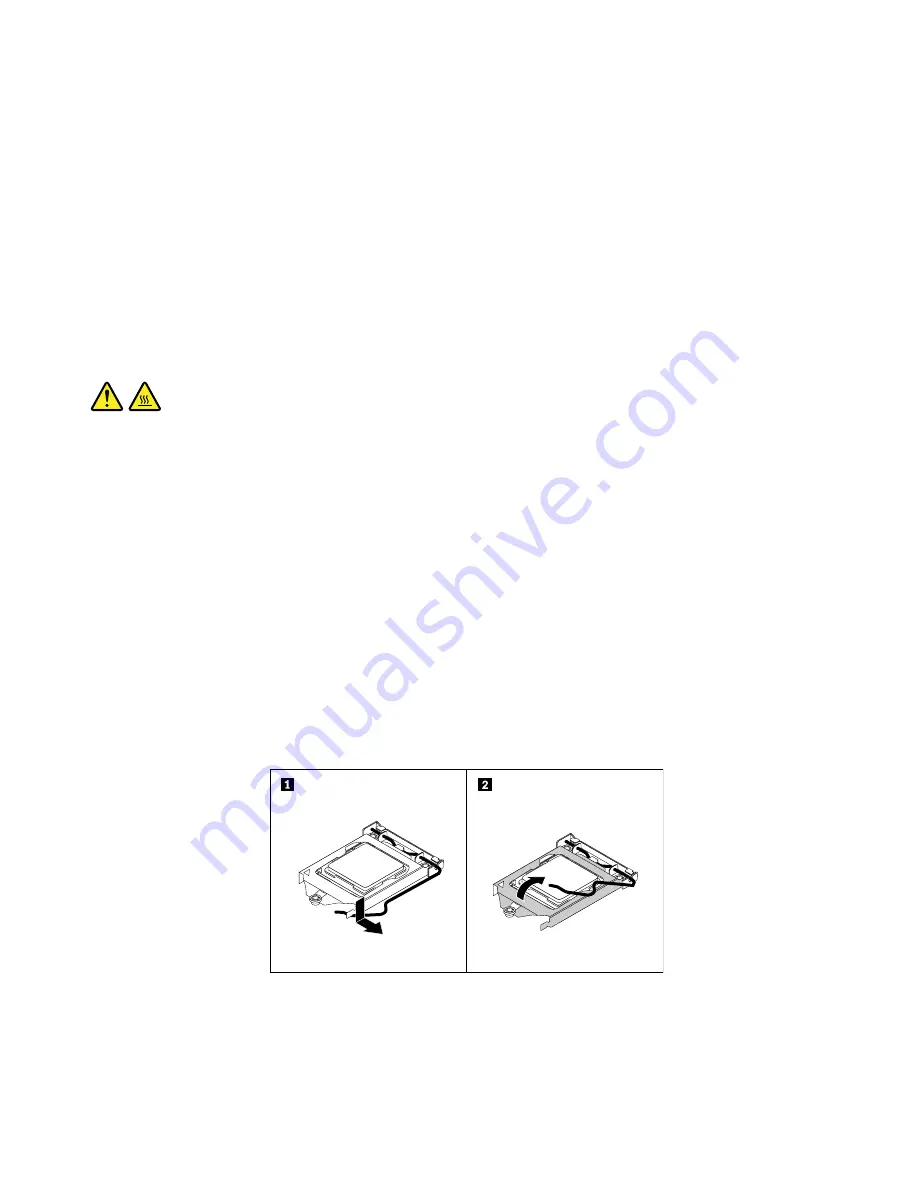
8. Press the small handle downward to release it from the retainer, and then open the retainer to access
the microprocessor.
Figure 51. Accessing the microprocessor
9. Lift the microprocessor straight up and out of the microprocessor socket.
Notes:
114
ThinkCentre M900z Hardware Maintenance Manual
Содержание ThinkCentre M900z 10F2
Страница 1: ...ThinkCentre M900z Hardware Maintenance Manual Machine Types 10F2 10F3 10F4 and 10F5 ...
Страница 6: ...iv ThinkCentre M900z Hardware Maintenance Manual ...
Страница 8: ...vi ThinkCentre M900z Hardware Maintenance Manual ...
Страница 16: ...8 ThinkCentre M900z Hardware Maintenance Manual ...
Страница 20: ...12 ThinkCentre M900z Hardware Maintenance Manual ...
Страница 21: ...1 2 Chapter 1 Read this first Important safety information 13 ...
Страница 22: ...1 2 14 ThinkCentre M900z Hardware Maintenance Manual ...
Страница 27: ...1 2 Chapter 1 Read this first Important safety information 19 ...
Страница 28: ...1 2 20 ThinkCentre M900z Hardware Maintenance Manual ...
Страница 31: ...Chapter 1 Read this first Important safety information 23 ...
Страница 40: ...31 32 ThinkCentre M900z Hardware Maintenance Manual ...
Страница 50: ...42 ThinkCentre M900z Hardware Maintenance Manual ...
Страница 66: ...58 ThinkCentre M900z Hardware Maintenance Manual ...
Страница 128: ...120 ThinkCentre M900z Hardware Maintenance Manual ...
Страница 136: ...128 ThinkCentre M900z Hardware Maintenance Manual ...
Страница 138: ...China RoHS 130 ThinkCentre M900z Hardware Maintenance Manual ...
Страница 139: ...Appendix D China Energy Label Copyright Lenovo 2015 131 ...
Страница 140: ...132 ThinkCentre M900z Hardware Maintenance Manual ...
Страница 142: ...134 ThinkCentre M900z Hardware Maintenance Manual ...
Страница 145: ......
Страница 146: ......