


2. Remove the computer cover. See “Removing the computer cover” on page 71.
3. Disconnect the power supply assembly cables from all drives and from the 24-pin power connector and
4-pin power connector on the system board. See “Locating parts on the system board” on page 69.
Note:
You might also need to release the power supply assembly cables from some cable clips or ties
that secure the cables to the chassis.
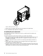
4. Lay the computer on its side and remove the four screws that secure the power supply assembly. Then,
slide the power supply assembly to the front of the chassis.
Figure 17. Removing the power supply assembly screws
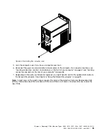
5. Pivot the power supply assembly as shown and then lift the power supply assembly to remove it
from the chassis.
Figure 18. Removing the power supply assembly
80
ThinkCentre Hardware Maintenance Manual
Содержание ThinkCentre M70e
Страница 2: ......
Страница 8: ...vi ThinkCentre Hardware Maintenance Manual ...
Страница 17: ...Chapter 2 Safety information 9 ...
Страница 18: ... 18 kg 37 lbs 32 kg 70 5 lbs 55 kg 121 2 lbs 1 2 PERIGO 10 ThinkCentre Hardware Maintenance Manual ...
Страница 21: ...Chapter 2 Safety information 13 ...
Страница 22: ...1 2 14 ThinkCentre Hardware Maintenance Manual ...
Страница 23: ...Chapter 2 Safety information 15 ...
Страница 29: ...Chapter 2 Safety information 21 ...
Страница 33: ...Chapter 2 Safety information 25 ...
Страница 40: ...32 ThinkCentre Hardware Maintenance Manual ...
Страница 74: ...66 ThinkCentre Hardware Maintenance Manual ...
Страница 104: ...96 ThinkCentre Hardware Maintenance Manual ...
Страница 402: ...394 ThinkCentre Hardware Maintenance Manual ...
Страница 407: ......
Страница 408: ...Part Number 71Y8558 Printed in USA 1P P N 71Y8558 71Y8558 ...