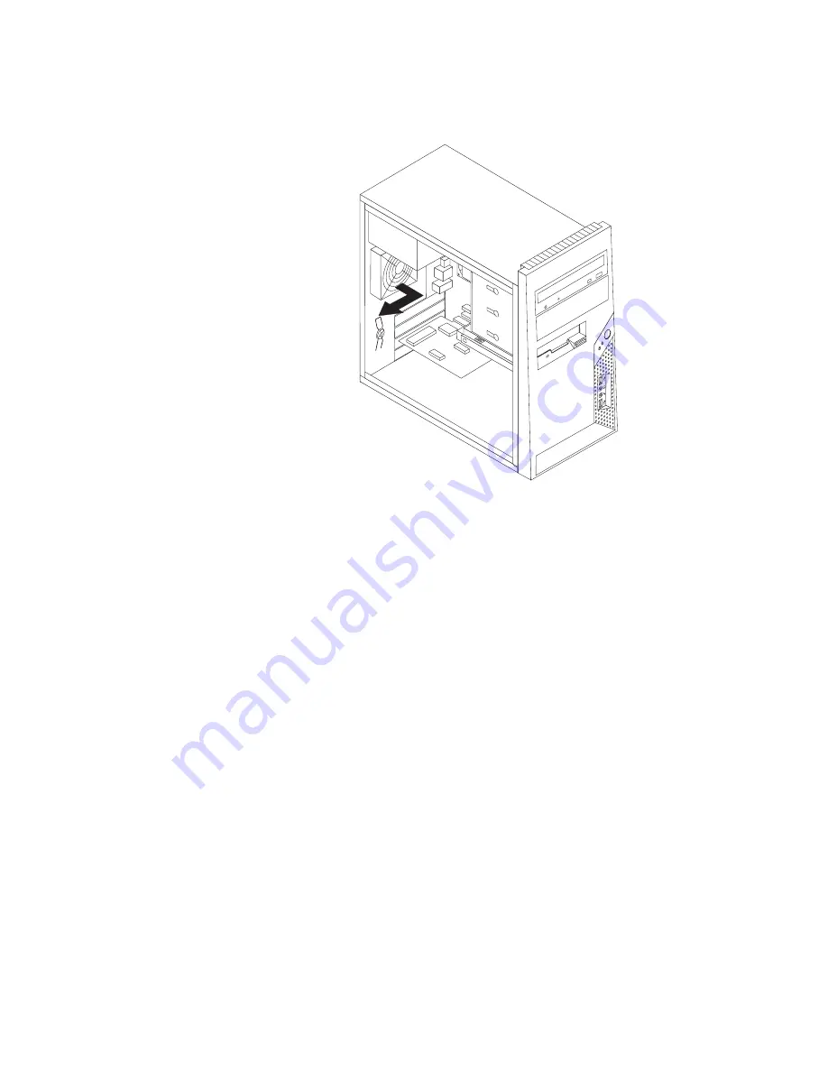
background image

4.


The


rear


fan


assembly


is


attached


to


the


chassis


by


four


rubber


mounts.


Remove


the


rear


fan


assembly


by


gently


pulling


it


out


of


the


chassis.


5.


Install


the


new


rear


fan


assembly


by


aligning


the


rubber


mounts


of


the


rear


fan


assembly


with


the


holes


on


the


chassis


and


push


the


rubber


mounts


through


the


holes.


Figure


37.


Removing


the


rear


fan


assembly


Chapter


3.


Installing


options


and


replacing


hardware


41

Содержание ThinkCentre M58p 3063

Страница 1: ...ThinkCentre Hardware Installation and Replacement Guide Machine Types 6138 6209 6239 6302 7188 7244 7347 7355 7358 7373 7484 7628 7635 7639 9960 and 9965 ...

Страница 2: ......

Страница 3: ...ThinkCentre Hardware Installation and Replacement Guide ...

Страница 4: ...oftware and services have been developed exclusively at private expense and are sold to governmental entities as commercial items as defined by 48 C F R 2 101 with limited and restricted rights to use reproduction and disclosure LIMITED AND RESTRICTED RIGHTS NOTICE If products data computer software or services are delivered pursuant a General Services Administration GSA contract use reproduction ...

Страница 5: ...ng internal drives 18 Replacing the battery 22 Replacing the power supply 23 Replacing the heat sink and fan assembly 25 Replacing the primary hard disk drive 26 Replacing the secondary hard disk drive 30 Replacing an optical drive 32 Replacing the diskette drive 34 Replacing a memory module 35 Replacing an adapter card 37 Replacing the front fan assembly 39 Replacing the rear fan assembly 40 Repl...

Страница 6: ...iv Hardware Installation and Replacement Guide ...

Страница 7: ...lling the primary hard disk drive into bracket 28 23 Installing the primary hard disk drive and bracket 29 24 Removing secondary hard disk drive 31 25 Installing the secondary hard disk drive into bracket 31 26 Installing the secondary hard disk drive and drive cage 32 27 Removing the optical drive 33 28 Retainer bracket for optical drive 33 29 Removing the diskette drive 34 30 Retainer bracket fo...

Страница 8: ...vi Hardware Installation and Replacement Guide ...

Страница 9: ...fety and Warranty Guide that you received with this product for the latest safety information Reading and understanding this safety information reduces the risk of personal injury and or damage to your product If you no longer have a copy of the ThinkCentre Safety and Warranty Guide you can obtain one online from the Lenovo Support Web site at http www lenovo com support Copyright Lenovo 2008 1 ...

Страница 10: ...2 Hardware Installation and Replacement Guide ...

Страница 11: ... supply v Heat sink and fan assembly v Primary hard disk drive v Secondary hard disk drive v Optical drive v Diskette drive v Memory module v Adapter card v Front fan assembly v Rear fan assembly v Internal speaker v Keyboard v Mouse Additional information resources If you have Internet access the most up to date information for your computer is available at http www lenovo com support You can fin...

Страница 12: ...m boards and microprocessors by the edges Never touch any exposed circuitry v Prevent others from touching the parts and other computer components v Before you replace a new part touch the static protective package containing the part to a metal expansion slot cover or other unpainted metal surface on the computer for at least two seconds This reduces static electricity in the package and your bod...

Страница 13: ...ols and connectors on the front of your computer Figure 1 shows the location of the controls and connectors on the front of your computer Note Not all computer models have the following controls and connectors 1 USB connector 3 Microphone connector 2 Headphone connector 4 USB connector Figure 1 Controls and connectors Chapter 2 Overview 5 ...

Страница 14: ... connectors 2 2 Power cord connector 11 Microphone connector 3 Standard mouse connector 12 Audio line out connector 4 Standard keyboard connector 13 Audio line in connector 5 VGA monitor connector 14 PCI Express x16 graphics adapter card slot 6 Serial port 15 PCI Express x1 adapter card slot 7 DisplayPort connector 16 Adapter card slots 2 8 USB connectors 4 17 Second serial port some models 9 Ethe...

Страница 15: ...u have more than eight USB devices you can purchase a USB hub which you can use to connect additional USB devices Ethernet connector Used to attach an Ethernet cable for a local area network LAN Note To operate the computer within FCC Class B limits use a Category 5 Ethernet cable Audio line out connector Used to send audio signals from the computer to external devices such as powered stereo speak...

Страница 16: ...your computer 1 Microprocessor heat sink and heat sink fan assembly 6 PCI Express x16 graphics adapter card slot 2 Memory slots 4 7 Cover presence Intrusion switch 3 PCI Express x1 adapter card slot 8 Rear system fan 4 Adapter card 9 Power supply 5 Adapter card slot Figure 3 Component locations 8 Hardware Installation and Replacement Guide ...

Страница 17: ...nector 6 Memory slot 4 20 Internal speaker connector 7 24 pin power connector 21 Adapter card slots 2 8 Thermal sensor connector 22 Cover presence Intrusion switch connector 9 Diskette drive connector 23 PCI Express x1 adapter card slot 10 SATA connectors 3 24 PCI Express x16 graphics adapter card slot 11 Parallel LPT connector 25 Battery 12 Power fan connector 26 System fan connector 13 eSATA con...

Страница 18: ...10 Hardware Installation and Replacement Guide ...

Страница 19: ...r of your computer on page 6 and Locating controls and connectors on the front of your computer on page 5 to identify the required connector and then use the instructions that are included with the option to help you make the connection and install any software or device drivers that are required for the option Removing the cover CAUTION Turn off the computer and wait three to five minutes to let ...

Страница 20: ...6 Press the cover release button on the side of the cover and slide the computer cover to the rear to remove Figure 5 Removing the computer cover 12 Hardware Installation and Replacement Guide ...

Страница 21: ... outward Carefully set the bezel to the side without disconnecting the power switch and LED assembly cable 3 To reinstall the bezel align the plastic tabs on the right side of the bezel with the corresponding holes in the chassis then pivot the bezel inward until it snaps into position on the left side 4 To complete the installation go to Chapter 4 Completing the parts replacement on page 47 Figur...

Страница 22: ...ing guidelines v Use 1 8 V 240 pin DDR3 SDRAM double data rate 3 synchronous dynamic random access memory v Use 1 0 GB or 2 0 GB memory modules in any combination up to a maximum of 8 0 GB Note Only DDR3 SDRAM DIMMs can be used 1 Remove the computer cover See Removing the cover on page 11 Note For this procedure it helps to lay the computer on its side 2 Locate the memory slots See Identifying par...

Страница 23: ...e aligns correctly with the slot key 2 on the system board Push the memory module straight down into the slot until the retaining clips close 5 Go to Chapter 4 Completing the parts replacement on page 47 Figure 8 Installing the memory module Chapter 3 Installing options and replacing hardware 15 ...

Страница 24: ...one for a PCI Express x16 graphics adapter card and one for a PCI Express x1 adapter card To install an adapter card 1 Remove the computer cover See Removing the cover on page 11 2 At the rear of the computer press the release button 1 to open the adapter latch 2 and remove the slot cover Figure 9 Opening the adapter latch 16 Hardware Installation and Replacement Guide ...

Страница 25: ... Pivot the adapter latch to the closed position to secure the adapter What to do next v To work with another option go to the appropriate section v To complete the installation go to Chapter 4 Completing the parts replacement on page 47 Figure 10 Closing the adapter latch Chapter 3 Installing options and replacing hardware 17 ...

Страница 26: ...es are also referred to as integrated drive electronics IDE drives Internal drives are installed in bays In this book the bays are referred to as bay 1 bay 2 and so on When you install an internal drive it is important to note the type and size of the drive that you can install in each bay Also it is important to correctly connect the internal drive cables to the installed drive Drive specificatio...

Страница 27: ...VD drive v 5 25 inch removable media drive v 3 5 inch hard disk drive requires a Universal Adapter Bracket 5 25 to 3 5 inch 3 Bay 3 Maximum height 25 8 mm 1 0 inch 3 5 inch diskette drive preinstalled in some models 4 Bay 4 Maximum height 25 8 mm 1 0 inch 3 5 inch primary SATA hard disk drive preinstalled 5 Bay 5 optional Maximum height 25 8 mm 1 0 inch 3 5 inch secondary SATA hard disk drive prei...

Страница 28: ... upper drive cage 3 Remove the metal static shield from the drive bay using your fingers to pull it outward 4 If you are installing a drive with accessible media such as an optical drive remove the plastic panel in the bezel for bay 2 by squeezing the plastic tabs that secure the panel on the inside of the bezel 5 Remove the retainer bracket from the upper drive cage by sliding it downward Figure ...

Страница 29: ...f the bezel with the corresponding holes in the chassis then pivot the bezel inward until it snaps into position on the left side 10 Continue at Connecting a serial ATA drive Connecting a serial ATA drive A serial optical drive or an additional hard disk drive can be connected to any available SATA connector 1 Locate the signal cable that comes with the new drive 2 Locate an available SATA connect...

Страница 30: ...ttery normally requires no charging or maintenance throughout its life however no battery lasts forever If the battery fails the date time and configuration information including passwords are lost An error message is displayed when you turn on the computer Refer to the Lithium battery notice in the ThinkCentre Safety and Warranty Guide for information about replacing and disposing of the battery ...

Страница 31: ...User Guide Replacing the power supply Attention Do not open your computer or attempt any repair before reading the Important safety information in the ThinkCentre Safety and Warranty Guide that came with your computer To obtain a copy of the ThinkCentre Safety and Warranty Guide go to http www lenovo com support This section provides instructions on how to replace the power supply 1 Remove the com...

Страница 32: ...power supply connector to each of the drives 9 If your computer has a voltage selection switch ensure that you set the voltage selection switch to match the voltage available at your electrical outlet If necessary use a ballpoint pen to slide the switch to a different position v If the voltage supply range in your local country or region is 100 127 V AC set the switch to 115 V v If the voltage sup...

Страница 33: ...ee Removing the cover on page 11 2 Lay the computer on its side 3 Locate the heat sink and fan assembly See Identifying parts on the system board on page 9 4 Disconnect the heat sink and the fan assembly cable from the microprocessor fan connector on the system board 5 Remove the four screws 1 that secure the heat sink and fan assembly to the system board 6 Lift the failing heat sink and fan assem...

Страница 34: ...d Warranty Guide go to http www lenovo com support This section provides instructions on how to replace the primary hard disk drive Important When you receive a new hard disk drive you also receive a set of Product Recovery discs The set of Product Recovery discs will enable you to restore the contents of the hard disk drive to the same state as when your computer was originally shipped from the f...

Страница 35: ...ly sliding it outward 6 Pull on the blue handle 3 to release and remove the hard disk drive from the drive cage 7 Remove the hard disk drive from the blue plastic bracket by flexing the sides of the bracket enough to slide it free of the hard disk drive Figure 21 Removing the primary hard disk drive Chapter 3 Installing options and replacing hardware 27 ...

Страница 36: ...4 on the bracket with the holes in the hard disk drive Do not touch the circuit board 5 on the bottom of the hard disk drive 9 Slide the new hard disk drive into the drive cage until it snaps into position Figure 22 Installing the primary hard disk drive into bracket 28 Hardware Installation and Replacement Guide ...

Страница 37: ...tch 2 pivot the drive cage into place and then slide it forward until it snaps into position Note There are two arrows one on the upper drive cage and one on the hard disk drive cage The arrows are aligned when the hard disk drive is in the proper position 13 Go to Chapter 4 Completing the parts replacement on page 47 Figure 23 Installing the primary hard disk drive and bracket Chapter 3 Installin...

Страница 38: ...When you receive a new hard disk drive you also receive a set of Product Recovery discs The set of Product Recovery discs will enable you to restore the contents of the hard disk drive to the same state as when your computer was originally shipped from the factory For more information on recovering factory installed software refer to Recovering software in your ThinkCentre User Guide To replace th...

Страница 39: ...f the bracket enough to slide it free of the hard disk drive 8 To install the new hard disk drive into the blue bracket flex the bracket and align pin 1 pin 2 pin 3 and pin 4 on the bracket with the holes in the hard disk drive Do not touch the circuit board 5 on the bottom of the hard disk drive Figure 24 Removing secondary hard disk drive Figure 25 Installing the secondary hard disk drive into b...

Страница 40: ... an optical drive Attention Do not open your computer or attempt any repair before reading the Important safety information in the ThinkCentre Safety and Warranty Guide that came with your computer To obtain a copy of the ThinkCentre Safety and Warranty Guide go to http www lenovo com support This section provides instructions on how to replace an optical drive 1 Remove the computer cover See Remo...

Страница 41: ...cket from the drive being replaced and install it on the new drive 5 Slide the new optical drive into the bay from the front until it snaps into position 6 Connect the signal and power cables to the drive 7 Go to Chapter 4 Completing the parts replacement on page 47 Figure 27 Removing the optical drive Figure 28 Retainer bracket for optical drive Chapter 3 Installing options and replacing hardware...

Страница 42: ...ee Removing and replacing the front bezel on page 13 3 Disconnect the signal and power cables from the rear of the diskette drive 4 Press the release button and slide the diskette drive out the front of the computer 5 Remove the retainer bracket from the failing diskette drive and install it on the new diskette drive 6 Slide the new diskette drive into the drive bay until it snaps into position 7 ...

Страница 43: ... section provides instructions on how to replace a memory module Note Your computer can support a maximum of four memory modules 1 Remove the computer cover See Removing the cover on page 11 Note For this procedure it helps to lay the computer on its side 2 Locate the memory slots See Identifying parts on the system board on page 9 3 Remove the memory module being replaced by opening the retaining...

Страница 44: ...ry module aligns correctly with the slot key 2 on the system board Push the memory module straight down into the slot until the retaining clips close 5 Go to Chapter 4 Completing the parts replacement on page 47 Figure 32 Installing the memory module 36 Hardware Installation and Replacement Guide ...

Страница 45: ...afety and Warranty Guide go to http www lenovo com support This section provides instructions on how to replace an adapter card 1 Remove the computer cover See Removing the cover on page 11 2 At the rear of the computer press the release button 1 to open the adapter latch 2 and remove the adapter card by pulling it straight out of the adapter card slot Figure 33 Removing the adapter card Chapter 3...

Страница 46: ...ot 5 Ensure the adapter card is fully seated into the adapter card slot 6 At the rear of the computer pivot the adapter latch to the closed position to secure the adapter card 7 Go to Chapter 4 Completing the parts replacement on page 47 Figure 34 Install a new adapter card 38 Hardware Installation and Replacement Guide ...

Страница 47: ... page 11 2 Remove the front bezel See Removing and replacing the front bezel on page 13 3 Disconnect the front fan assembly cable from the power fan connector on the system board See Identifying parts on the system board on page 9 4 The front fan assembly is attached to the chassis by four rubber mounts Remove the front fan assembly by gently pulling it out of the chassis 5 Install the new front f...

Страница 48: ...fety and Warranty Guide that came with your computer To obtain a copy of the ThinkCentre Safety and Warranty Guide go to http www lenovo com support This section provides instructions on how to replace the rear fan assembly 1 Remove the computer cover See Removing the cover on page 11 2 Locate the rear fan assembly See Locating components on page 8 3 Disconnect the rear fan assembly cable from the...

Страница 49: ... by gently pulling it out of the chassis 5 Install the new rear fan assembly by aligning the rubber mounts of the rear fan assembly with the holes on the chassis and push the rubber mounts through the holes Figure 37 Removing the rear fan assembly Chapter 3 Installing options and replacing hardware 41 ...

Страница 50: ...ssembly is in place 7 Connect the rear fan assembly cable to the system fan connector on the system board 8 Go to Chapter 4 Completing the parts replacement on page 47 Figure 38 Replacing the rear fan assembly 42 Hardware Installation and Replacement Guide ...

Страница 51: ...on provides instructions on how to replace the internal speaker 1 Remove the computer cover See Removing the cover on page 11 2 Locate the speaker connector on the system board See Identifying parts on the system board on page 9 3 Disconnect the speaker cable from the system board 4 Push the metal tab on the top of the internal speaker outward and slide the internal speaker upward to completely re...

Страница 52: ...r until it snaps into position 6 Connect the speaker cable to the system board See Identifying parts on the system board on page 9 7 Go to Chapter 4 Completing the parts replacement on page 47 Figure 40 Replacing the internal speaker 44 Hardware Installation and Replacement Guide ...

Страница 53: ...ctors on the rear of your computer on page 6 or Locating controls and connectors on the front of your computer on page 5 4 Disconnect the failing keyboard cable from the computer 5 Connect the new keyboard to the appropriate connector on the computer 6 Go to Chapter 4 Completing the parts replacement on page 47 Replacing the mouse Attention Do not open your computer or attempt any repair before re...

Страница 54: ...ctors on the rear of your computer on page 6 or Locating controls and connectors on the front of your computer on page 5 4 Disconnect the failing mouse cable from the computer 5 Connect the new mouse to the appropriate connector on the computer 6 Go to Chapter 4 Completing the parts replacement on page 47 Figure 42 Mouse connectors 46 Hardware Installation and Replacement Guide ...

Страница 55: ...no tools or loose screws are left inside your computer See Locating components on page 8 for the location of various components 2 Position the computer cover on the chassis so that the rail guides on the bottom of the computer cover engage the rails Then push the computer cover closed until it snaps into position 3 If the cover is secured with thumbscrews install them 4 If a cover lock is installe...

Страница 56: ... the CRU or will come a few days after the CRU arrives Obtaining device drivers You can obtain device drivers for operating systems that are not preinstalled at http www lenovo com support Installation instructions are provided in readme files with the device driver files 48 Hardware Installation and Replacement Guide ...

Страница 57: ...r cables Integrated cable lock An integrated cable lock sometimes referred to as the Kensington lock can be used to secure your computer to a desk table or other non permanent fixture The cable lock attaches to a security slot at the rear of your computer and is operated with a key See Figure 44 The cable lock also locks the buttons used to open the computer cover This is the same type of lock use...

Страница 58: ... complete the installation go to Chapter 4 Completing the parts replacement on page 47 Erasing a lost or forgotten password clearing CMOS This section contains instructions on erasing some lost or forgotten passwords such as a user password For more information about lost or forgotten passwords go to the ThinkVantage Productivity Center program To erase a forgotten password 1 Remove the computer c...

Страница 59: ...5 Restart the computer leave it on for approximately 10 seconds Turn off the computer by holding the power switch for approximately 5 seconds The computer will turn off 6 Repeat step 1 and step 2 on page 50 7 Move the Clear CMOS Recovery jumper back to the standard position pin 1 and pin 2 8 Replace the computer cover and connect the power cord See Chapter 4 Completing the parts replacement on pag...

Страница 60: ...52 Hardware Installation and Replacement Guide ...

Страница 61: ...information could include technical inaccuracies or typographical errors Changes are periodically made to the information herein these changes will be incorporated in new editions of the publication Lenovo may make improvements and or changes in the product s and or the program s described in this publication at any time without notice The products described in this document are not intended for u...

Страница 62: ...copyright protection technology that is protected by method claims of certain U S patents and other intellectual property rights owned by Macrovision Corporation and other rights owners Use of this copyright protection technology must be authorized by Macrovision Corporation and is intended for home and other limited viewing uses only unless otherwise authorized by Macrovision Corporation Reverse ...

Страница 63: ...nstalling drive 20 installing options adapter card 16 internal drives 18 memory 14 security features 49 internal options installing 14 internal speaker replacing 43 K keyboard connector 7 keyboard replacing 45 L locating components 8 M memory module replacing 35 mouse connector 7 mouse replacing 45 N notice television output 54 notices 53 O optical drive replacing 32 options installing internal dr...

Страница 64: ...56 Hardware Installation and Replacement Guide ...

Страница 65: ......

Страница 66: ...Part Number 46R4720 Printed in USA 1P P N 46R4720 ...

Отзывы: