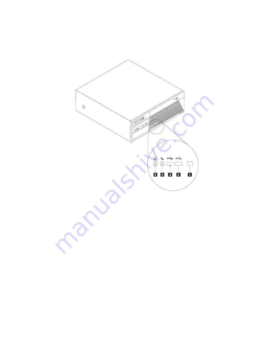
Lenovo ThinkCentre 8129 Скачать руководство пользователя страница 23

Locating


the


connectors


on


the


front


of


your


computer


The


following


illustration


shows


the


locations


of


the


connectors


on


the


front


of


the


computer.


Note:


Not


all


computer


models


will


have


the


following


connectors.

ThinkCentre

1
3
9
4


1

IEEE


1394


connector


4

Microphone


connector


2

USB


connector


5

Headphone


connector


3

USB


connector


Chapter


1.


Installing


options


7

Содержание ThinkCentre 8129

Страница 1: ...User Guide Types 8129 8132 8133 Types 8134 8135 8136 ThinkCentre ...

Страница 2: ......

Страница 3: ...User Guide Types 8129 8132 8133 Types 8134 8135 8136 ...

Страница 4: ...CTED RIGHTS Our products and or services are provided with RESTRICTED RIGHTS Use duplication or disclosure by the Government is subject to the GSA ADP Schedule contract with Lenovo Group Limited if any or the standard terms of this commercial license or if the agency is unable to accept this Program under these terms then we provide this Program under the provisions set forth in Commercial Compute...

Страница 5: ...lling security features 21 Padlock loop 21 Password protection 21 Changing the battery 21 Erasing a lost or forgotten password clearing CMOS 22 Replacing the cover and connecting the cables 23 Chapter 2 Using the Setup Utility program 25 Starting the Setup Utility program 25 Viewing and changing settings 25 Using passwords 25 User password 25 Administrator password 26 Setting changing and deleting...

Страница 6: ...iv User Guide ...

Страница 7: ...r computer product may contain a coin sized internal battery that provides power to your system clock even when the machine is unplugged so the battery safety information applies to all computers Conditions that require immediate action Products can become damaged due to misuse or neglect Some product damage is serious enough that the product should not be used again until it has been inspected an...

Страница 8: ...hat product until you can contact the product manufacturer for further instructions or until you get a suitable replacement General safety guidelines Always observe the following precautions to reduce the risk of injury and property damage Service Do not attempt to service a product yourself unless instructed to do so by the Customer Support Center Use only a service provider who is approved to re...

Страница 9: ...use a short circuit particularly if the cord or power adapter has been stressed by misuse Liquids can also cause gradual corrosion of the power cord terminals and or the connector terminals on the adapter which can eventually result in overheating Always connect power cords and signal cables in the correct order and ensure that all power cord connectors are securely and completely plugged into rec...

Страница 10: ...ct and disconnect the equipment from the electrical outlet Batteries All personal computers manufactured by Lenovo contain a non rechargeable coin cell battery to provide power to the system clock In addition many mobile products such as ThinkPad notebook PCs utilize a rechargeable battery pack to provide system power when in portable mode Batteries supplied by Lenovo for use with your product hav...

Страница 11: ... cover If possible avoid operating your computer within 2 feet of high traffic areas If you must operate your computer in or near a high traffic area you should inspect and if necessary clean your computer more frequently For your safety and to maintain optimum computer performance always follow these basic precautions with your desktop computer v Keep the cover closed whenever the computer is plu...

Страница 12: ...e covers unless instructed otherwise in the installation and configuration procedures v Connect and disconnect cables as described in the following table when installing moving or opening covers on this product or attached devices To connect 1 Turn everything OFF 2 First attach all cables to devices 3 Attach signal cables to connectors 4 Attach power cords to outlet 5 Turn device ON To disconnect ...

Страница 13: ...parately as options CD ROM drives and DVD ROM drives are laser products These drives are certified in the U S to conform to the requirements of the Department of Health and Human Services 21 Code of Federal Regulations DHHS 21 CFR Subchapter J for Class 1 laser products Elsewhere these drives are certified to conform to the requirements of the International Electrotechnical Commission IEC 825 and ...

Страница 14: ...s the following label attached Hazardous voltage current and energy levels are present inside any component that has this label attached There are no serviceable parts inside these components If you suspect a problem with one of these parts contact a service technician xii User Guide ...

Страница 15: ... your computer and starting the operating system It also includes basic troubleshooting information software recovery procedures help and service information and warranty information The Access IBM program on your desktop provides a link to more information about your computer If you have Internet access the most up to date information for your computer is available from the World Wide Web You can...

Страница 16: ...xiv User Guide ...

Страница 17: ...ion read Important safety information on page v These precautions and guidelines will help you work safely Features This section provides an overview of the computer features and preinstalled software System information The following information covers a variety of models For information for your specific model use the Setup Utility See Chapter 2 Using the Setup Utility program on page 25 Micropro...

Страница 18: ... Broadcom Ethernet controller some models v Peripheral Component Interconnect PCI V 90 Data Fax modem some models System management features v Remote Program Load RPL and Dynamic Host Configuration Protocol DHCP v Wake on LAN v Wake on Ring in the Setup Utility program this feature is called Serial Port Ring Detect for an external modem v Remote Administration v Automatic power on startup v System...

Страница 19: ...vice Preinstalled software Your computer might come with preinstalled software If it does an operating system device drivers to support built in features and other support programs are included Operating systems preinstalled varies by model type Note Not all countries or regions will have these operating systems v Microsoft Windows XP Home v Microsoft Windows XP Professional Operating systems cert...

Страница 20: ... 0 32 kVA Note Power consumption and heat output vary depending on the number and type of optional features installed and the power management optional features in use Heat output approximate in British thermal units Btu per hour Minimum configuration 256 Btu hr 75 watts Maximum configuration 1058 Btu hr 310 watts Airflow Approximately 1 13 cubic meters per minute 40 cubic feet per minute maximum ...

Страница 21: ...e or DVD drive some models Hard disk drive Diskette drive or another removable media drive For the latest information about available options see the following World Wide Web pages v http www lenovo com think en v http www lenovo com think support You also can obtain information by calling the following telephone numbers v Within the United States call 1 800 426 2968 your Lenovo reseller or Lenovo...

Страница 22: ...er for at least two seconds This reduces static electricity in the package and your body v When possible remove the option and install it directly in the computer without setting the option down When this is not possible place the static protective package that the option came in on a smooth level surface and place the option on it v Do not place the option on the computer cover or other metal sur...

Страница 23: ... shows the locations of the connectors on the front of the computer Note Not all computer models will have the following connectors ThinkCentre 1 3 9 4 1 IEEE 1394 connector 4 Microphone connector 2 USB connector 5 Headphone connector 3 USB connector Chapter 1 Installing options 7 ...

Страница 24: ...onnector some models 12 Audio line out connector 4 Standard mouse connector 13 Microphone connector 5 Ethernet connector 14 Serial connector 6 Parallel connector 15 VGA monitor connector 7 Audio line in connector 16 USB connectors 8 Serial connector some models 17 USB connectors 9 Voltage selection switch 18 Standard keyboard connector Note Some connectors on the rear of the computer are color cod...

Страница 25: ...nector Used to attach a keyboard that uses a standard keyboard connector Mouse connector Used to attach a mouse trackball or other pointing device that uses a standard mouse connector Parallel connector Used to attach a parallel printer parallel scanner or other devices that use a 25 pin parallel connector Serial connectors Used to attach an external modem serial printer or other devices that use ...

Страница 26: ...CDs or tapes from the drives and turn off all attached devices and the computer 2 Unplug all power cords from electrical outlets 3 Disconnect all cables attached to the computer This includes power cords input output I O cables and any other cables that are connected to the computer 4 Press the buttons on the sides of the computer and pivot the rear end of the cover up toward the front of the comp...

Страница 27: ...s x16 graphics adapter connector some models 7 Microprocessor and heat sink 4 PCI adapter connector 8 Hard disk drive Identifying parts on the system board The system board sometimes called the planar or motherboard is the main circuit board in your computer It provides basic computer functions and supports a variety of devices that are factory installed or that you can install later Chapter 1 Ins...

Страница 28: ...r 9 System fan connector 20 Microprocessor heat sink 10 SATA connectors 21 12v power connector 11 PCI Express x16 graphics adapter connector some models 22 Diskette drive connector Installing memory Your computer has four connectors for installing dual inline memory modules DIMMs that provide up to a maximum of 4 0 GB of system memory When installing DDR2 type memory modules the following rules ap...

Страница 29: ...oard X X X X X X X X X X X X X X X X X X 4 Locate the memory connectors See Identifying parts on the system board on page 11 5 Open the retaining clips 6 Make sure that the notch 1 on the memory module aligns correctly with the connector key 2 on the system board Push the memory module straight down into the connector until the retaining clips close Chapter 1 Installing options 13 ...

Страница 30: ...nd removing adapters Your computer has two expansion slots for PCI adapters one PCI Express x1 adapter connector and one PCI Express x16 graphics adapter connector You can install an adapter up to 340 mm 13 4 inches long in PCI connector 1 and PCI connector 2 To install an adapter 1 Remove the cover See Removing the cover on page 10 2 Rotate the drive bay assembly upward to gain access to the syst...

Страница 31: ...atic protective package 5 Install the adapter into the appropriate connector on the system board 6 Close the adapter slot cover latch X X X X X X X X X X X X X X X X X X What to do next v To work with another option go to the appropriate section v To complete the installation go to Replacing the cover and connecting the cables on page 23 Chapter 1 Installing options 15 ...

Страница 32: ...Removable media drives Note These different drives are also referred to as integrated drive electronics IDE drives Internal drives are installed in bays In this book the bays are referred to as bay 1 bay 2 and so on When you install an internal drive it is important to note what type and size of drive that you can install in each bay Also it is important to correctly connect the internal drive cab...

Страница 33: ...rd disk drive requires a Universal Adapter Bracket 5 25 to 3 5 inch Optical drive such as CD drive or DVD drive 4 Bay 4 Maximum height 25 8 mm 1 0 in 3 5 inch hard disk drive preinstalled You can obtain a Universal Adapter Bracket 5 25 to 3 5 inch from a local computer retailer or by contacting the Customer Support Center Notes 1 Drives that are greater than 43 0 mm 1 7 in high cannot be installed...

Страница 34: ...slave device Note A serial ATA hard disk drive does not need to be set as either a master or a slave device v If it is the first CD drive or DVD drive set it as a master device v If it is an additional CD drive or DVD drive set it as a slave device v If it is an additional parallel ATA hard disk drive set it as a slave device Refer to the documentation that comes with your drive for master slave j...

Страница 35: ...er cable that connects to the power supply and a signal cable that connects to the system board v A parallel ATA hard disk drive requires a four wire power cable v A serial ATA hard disk drive requires a five wire power cable The steps to connect a drive are different depending on the type of drive you are connecting Use one of the following procedures for your drive connection Chapter 1 Installin...

Страница 36: ...entifying parts on the system board on page 11 2 Connect the extra connector on the signal cable to the new drive 3 Your computer has extra power connectors for additional drives Connect a power connector to the drive Connecting a serial ATA hard disk drive A serial hard disk drive can be connected to any available SATA connector 1 Locate the signal cable that comes with the new drive 2 Locate an ...

Страница 37: ...k loop does not interfere with the computer cables Password protection To deter unauthorized use of your computer you can use the Setup Utility program to set a password See Using passwords on page 25 What to do next v To work with another option go to the appropriate section v To complete the installation go to Replacing the cover and connecting the cables on page 23 Changing the battery Your com...

Страница 38: ... gain access to the battery See Installing adapters on page 14 for instructions for replacing adapters 8 Replace the cover and plug in the power cord See Replacing the cover and connecting the cables on page 23 Note When the computer is turned on for the first time after battery replacement an error message might be displayed This is normal after replacing the battery 9 Turn on the computer and al...

Страница 39: ...ver and connecting the cables After working with options you need to install any removed parts replace the cover and reconnect any cables including telephone lines and power cords Also depending on the option that is installed you might need to confirm the updated information in the Setup Utility program To replace the cover and connect cables to your computer 1 Ensure that all components have bee...

Страница 40: ...24 User Guide ...

Страница 41: ...d or an administrator password has been set the configuration settings in the Setup Utility program menu cannot be changed without a password See Using passwords for more information The Setup Utility might start automatically when POST detects that hardware has been removed or new hardware has been installed in your computer Viewing and changing settings The Setup Utility program menu lists items...

Страница 42: ...ong password three times you must turn the computer off and start again If both the user and administrator passwords are set you can type either password However to change any configuration settings you must use your administrator password Setting changing and deleting a password To set change or delete a password do the following Note A password can be any combination of up to 12 characters A Z a...

Страница 43: ...p device If your computer does not start up boot from a device such as the CD ROM diskette or hard disk as expected use one of the following procedures to select a startup device Selecting a temporary startup device Use this procedure to startup from any boot device Note Not all CDs hard disks and diskettes are startable bootable 1 Turn off your computer 2 Press and hold the F12 key as you turn on...

Страница 44: ...quence the Automatic Startup Sequence and the Error Startup Sequence 5 Select Exit from the Setup Utility menu and then Save Settings If you have changed these settings and want to return to the default settings select Load Default Settings on the Exit menu Exiting from the Setup Utility program When you finish viewing or changing settings press Esc to return to the Setup Utility program menu you ...

Страница 45: ...ons for using the system program updates are available in a txt file that is included with the update files For most models you can download either an update program to create a system program update flash diskette or an update program that can be run from the operating system Updating flashing BIOS from a diskette or CD ROM Important Start the Setup Utility program to view your system information...

Страница 46: ...ted flash update your computer might not restart correctly If this happens perform the following procedure also known as a Boot block Recovery 1 Turn off the computer and any attached devices such as printers monitors and external drives 2 Unplug all power cords from electrical outlets and remove the cover See Removing the cover on page 10 3 Rotate the drive bay assembly upward to gain access to t...

Страница 47: ...the surface on which you are using the mouse If you have a very intricate picture or pattern beneath the mouse it is difficult for the digital signal processor DSP to determine changes in the mouse position Cleaning a mouse with a ball If the pointer on the screen does not move smoothly with the mouse you might need to clean the mouse Note The following illustration might be slightly different fro...

Страница 48: ...llers 3 inside the ball cage This build up usually appears as a stripe running across the middle of the rollers 6 If the rollers are dirty clean them by using a cotton swab soaked in isopropyl rubbing alcohol Turn the rollers with your finger and continue swabbing them until all the dirt is removed Be sure the rollers are still centered in their channels after you clean them 7 Remove any fibers fr...

Страница 49: ...es one it is just like specifying a parameter of 0 Example ATH ENTER Basic AT commands In the following listings all default settings are printed in bold text Command Function A Manually answer incoming call A Repeat last command executed Do not precede A with AT or follow with ENTER D_ 0 9 A D and L last number redial P pulse dialing Note Pulse dialing is not supported for Australia New Zealand N...

Страница 50: ...turn to Data Mode O1 Return to Data Mode and initiate an equalizer retrain P Set Pulse dial as default Q_ Q0 Modem sends responses Sr Read and display value in register r Sr n Set register r to value n n 0 255 T Set Tone Dial as default V_ V0 Numeric responses V1 Word responses W_ W0 Report DTE speed only W1 Report line speed error correction protocol and DTE speed W2 Report DCE speed only X_ X0 H...

Страница 51: ...low control M_ M0 Asynchronous operation P_ P0 US setting for off hook to on hook ratio P1 UK and Hong Kong off hook to on hook ratio P2 Same as P0 setting but at 20 pulses per minute P3 Same as P1 setting but at 20 pulses per minute R_ R0 Reserved R1 CTS operates per flow control requirements S_ S0 Force DSR Signal High ON S1 DSR off in command mode on in on line mode T_ T0 Ends test in progress ...

Страница 52: ... Parameter b specifies automode operations where 0 automode disabled 1 automode enabled with V 8 V 32 Annex A Parameter c specifies the minimum connection data rate 300 56000 Parameter d specifies the maximum connection rate 300 56000 Parameter e specifies the codec type 0 Law and 1 A Law Parameter f specifies robbed bit signaling detection 0 detection disabled 1 detection enabled MNP V 42 V 42bis...

Страница 53: ... Set the polled station identification FCIG Report the polled station identification FCR Capability to receive FCR Capability to receive FCSI Report the called station ID FDCC DCE capabilities parameters FDCS Report current session FDCS Current session results FDIS Report remote capabilities FDIS Current sessions parameters FDR Begin or continue phase C receive data FDT Data transmission FDTC Repo...

Страница 54: ...ufacturer REV Identify Revision Level TL Audio output transmit level VBQ Query Buffer Size VBS Bits per sample ADPCM or PCM VBT Beep Tone Timer VCI Identify Compression Method VLS Voice line select VRA Ringback goes away timer VRN Ringback never came timer VRX Voice Receive Mode VSDB Silence deletion tuner VSK Buffer skid setting VSP Silence detection period VSR Sampling rate selection VSS Silence...

Страница 55: ...s not have Taxsignal switched OFF modem function may be impaired The impairment may be resolved by a filter with the following specifications Telekom PTT SCR BE Taximpulssperrfilter 12kHz PTT Art 444 112 7 Bakom 93 0291 Z N Appendix C Manual modem commands 39 ...

Страница 56: ...40 User Guide ...

Страница 57: ...This information could include technical inaccuracies or typographical errors Changes are periodically made to the information herein these changes will be incorporated in new editions of the publication Lenovo may make improvements and or changes in the product s and or the program s described in this publication at any time without notice The products described in this document are not intended ...

Страница 58: ...ight protection technology must be authorized by Macrovision Corporation and is intended for home and other limited viewing uses only unless otherwise authorized by Macrovision Corporation Reverse engineering or disassembly is prohibited Trademarks The following terms are trademarks of Lenovo in the United States other countries or both Lenovo ThinkCentre ThinkPad The following terms are trademark...

Страница 59: ...dapters 14 internal drives 17 memory 12 memory modules 12 installing options continued security features 21 K keyboard connector 9 L locating components 11 M memory dual inline memory modules DIMMs 12 installing 12 system 12 memory modules installing 12 modem Basic AT commands 33 Extended AT commands 35 Fax Class 1 commands 37 Fax Class 2 commands 37 MNP V 42 V 42bis V 44 commands 36 Voice command...

Страница 60: ...ecurity profile by device 27 serial connector 9 Setup Utility 25 system board connectors 12 identifying parts 11 location 12 memory 5 12 system programs 29 U USB connectors 9 using security profile by device 27 V video subsystem 2 44 User Guide ...

Страница 61: ......

Страница 62: ...Part Number 39J7694 Printed in USA 1P P N 39J7694 ...

Отзывы: