


8. Lift the failing heat sink assembly off the system board.
Notes:
a. You might have to gently twist the heat sink assembly to free it from the microprocessor.
b. Do not touch the thermal grease while handling the heat sink assembly.
9. To reinstall the heat sink assembly, position the new heat sink assembly on the system board so that the
five screws are aligned with the corresponding holes in the system board and computer main bracket.
10. Follow the sequence
1
,
2
,
3
,
4
on the heat sink assembly to tighten the four screws and install the
screw
5
to secure the heat sink assembly to the system board, as shown in Figure 20 “Loosing the
screws that secure the heat sink assembly to the system board” on page 79.
11. Reinstall the system board shield. See “Removing and reinstalling the system board shield” on page 76.
12. Go to “Completing the parts replacement” on page 96.
Replacing the microprocessor
Attention
Do not open your computer or attempt any repair before reading and understanding the “Important safety
information” in the
Safety, Warranty, and Setup Guide
that came with your computer. To obtain a copy of the
Safety, Warranty, and Setup Guide
, go to:
http://www.lenovo.com/support
This section provides instructions on how to replace the microprocessor.
CAUTION:
The heat sink and fan assembly might be very hot. Turn off the computer and wait three to five
minutes to let the computer cool before removing the computer cover.
To replace the microprocessor, do the following:
1. Remove all media from the drives and turn off all attached devices and the computer. Then, disconnect
all power cords from electrical outlets and disconnect all cables that are connected to the computer.
2. Place a soft, clean towel or cloth on the desk or other flat surface. Hold the sides of your computer and
gently lay it down so that the screen is against the surface and the cover is facing up.
3. Remove the computer cover. See “Removing the computer cover” on page 71.
4. Remove the VESA mount bracket. See “Removing and reinstalling the VESA mount bracket” on page 71.
5. Locate the microprocessor on the system board. See “Locating major FRUs and CRUs” on page 63.
6. Remove the system board shield. See “Removing and reinstalling the system board shield” on page 76.
7. Remove the heat sink assembly to gain access to the microprocessor. See “Replacing the heat sink
assembly” on page 78.
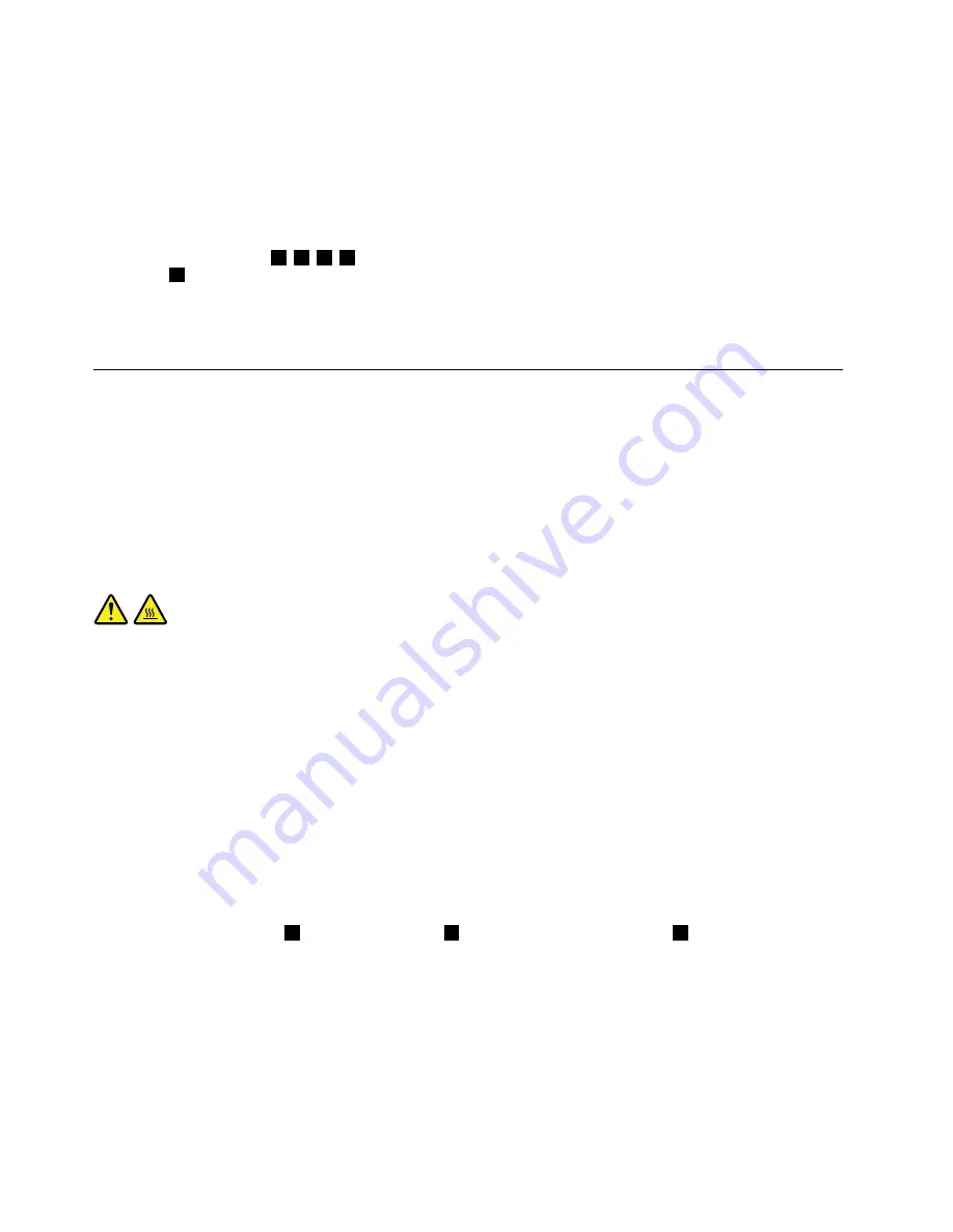
8. Press the small handle
1
to open the retainer
2
to access the microprocessor
3
.
80
Lenovo S710 All-In-OneHardware Maintenance Manual
Содержание S710
Страница 1: ...Lenovo S710 All In One Hardware Maintenance Manual Machine Types 10152 F0AG ...
Страница 2: ......
Страница 3: ...Lenovo S710 All In One Hardware Maintenance Manual Machine Types 10152 F0AG ...
Страница 8: ...2 Lenovo S710 All In OneHardware Maintenance Manual ...
Страница 15: ...Chapter 2 Safety information 9 ...
Страница 19: ...Chapter 2 Safety information 13 ...
Страница 20: ...1 2 14 Lenovo S710 All In OneHardware Maintenance Manual ...
Страница 21: ...1 2 Chapter 2 Safety information 15 ...
Страница 26: ...1 2 20 Lenovo S710 All In OneHardware Maintenance Manual ...
Страница 27: ...1 2 Chapter 2 Safety information 21 ...
Страница 30: ...24 Lenovo S710 All In OneHardware Maintenance Manual ...
Страница 34: ...28 Lenovo S710 All In OneHardware Maintenance Manual ...
Страница 66: ...60 Lenovo S710 All In OneHardware Maintenance Manual ...
Страница 70: ...Figure 3 Locating major FRUs and CRUs 64 Lenovo S710 All In OneHardware Maintenance Manual ...
Страница 104: ...98 Lenovo S710 All In OneHardware Maintenance Manual ...
Страница 117: ......
Страница 118: ......


