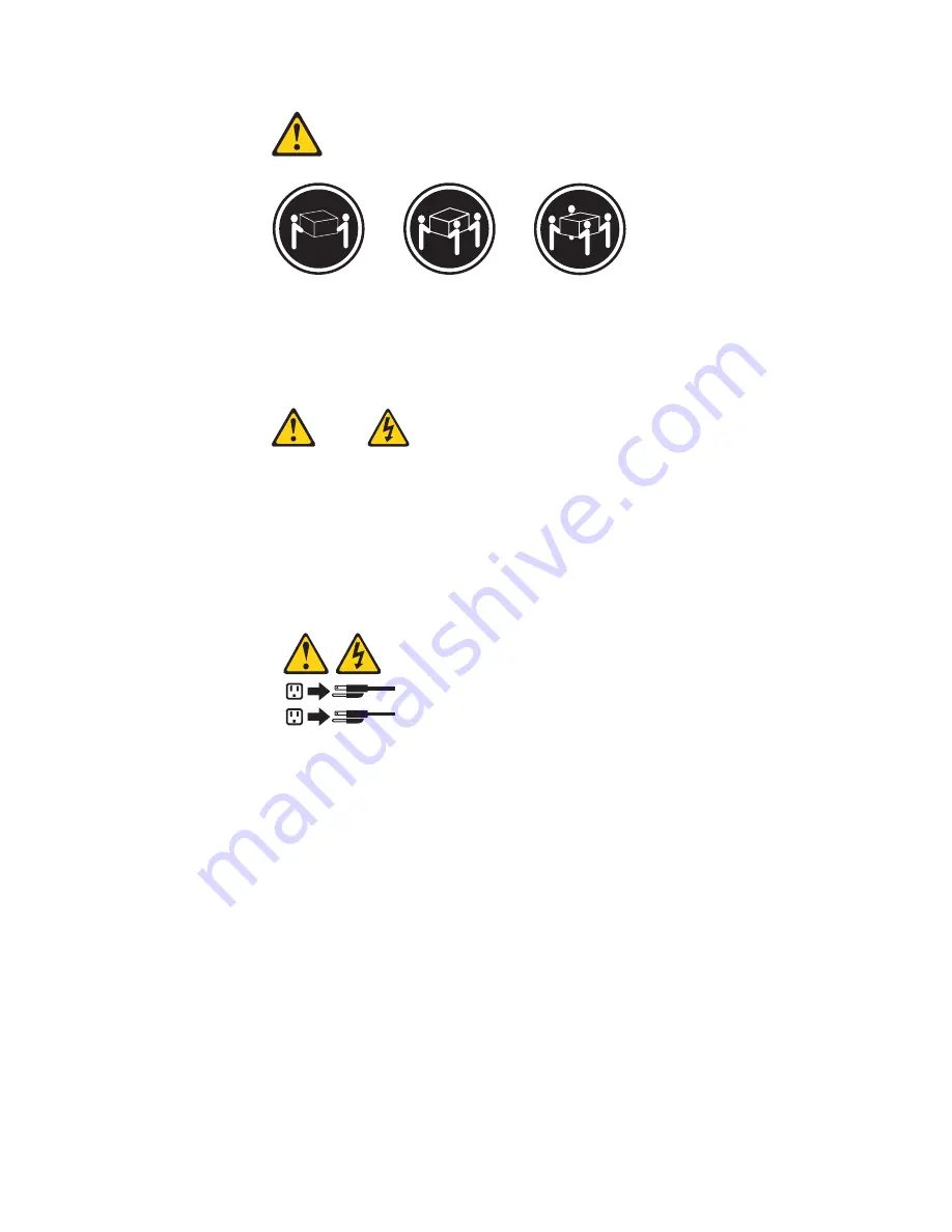
background image

18


kg


(37


lbs)


32


kg


(70.5


lbs)


55


kg


(121.2


lbs)


ATTENTION:


Soulevez


la


machine


avec


précaution.


ATTENTION:


L’interrupteur


de


contrôle


d’alimentation


de


l’unité


et


l’interrupteur


dubloc


d’alimentation


ne


coupent


pas


le


courant


électrique


alimentantl’unité.


En


outre,


le


système


peut


être


équipé


de


plusieurs


cordonsd’alimentation.


Pour


mettre


l’unité


hors


tension,


vous


devez


déconnectertous


les


cordons


de


la


source


d’alimentation.


1

2


Chapter


2.


Safety


information


23

Содержание Lenovo 3000 J Series

Страница 1: ......

Страница 2: ......

Страница 3: ...Hardware Maintenance Manual ...

Страница 4: ...computer software and services have been developed exclusively at private expense and are sold to governmental entities as commercial items as defined by 48 C F R 2 101 with limited and restricted rights to use reproduction and disclosure LIMITED AND RESTRICTED RIGHTS NOTICE If products data computer software or services are delivered pursuant a General Services Administration GSA contract use rep...

Страница 5: ...er 7 Symptom to FRU Index 55 Hard disk drive boot error 55 Power Supply Problems 55 Diagnostic error codes 56 Beep symptoms 77 POST error codes 78 Miscellaneous error messages 80 Undetermined problems 81 Chapter 8 Replacing FRUs Types 9680 9681 9682 9683 9684 and 9685 83 Rear connectors 84 Removing the cover 85 Locations 86 Locating parts on the system board 87 Machine types 9680 and 9681 87 Machi...

Страница 6: ... Machine Type 9685 186 Machine Type 9686 190 Machine Type 9687 196 Machine Type 9688 202 Machine Type 9689 207 Machine Type 9690 213 Machine Type 9691 220 Chapter 11 Additional Service Information 227 Security features 227 Hardware controlled Passwords 227 Operating system password 227 Vital product data 227 BIOS levels 227 Flash update procedures 227 Updating flashing BIOS from a CD ROM or disket...

Страница 7: ... also available at http www lenovo com support Important Safety Information Be sure to read all caution and danger statements in this book before performing any of the instructions Veuillez lire toutes les consignes de type DANGER et ATTENTION du présent document avant d exécuter les instructions Lesen Sie unbedingt alle Hinweise vom Typ ACHTUNG oder VORSICHT in dieser Dokumentation bevor Sie irge...

Страница 8: ...mplementation date and expects its suppliers to be ready to support Lenovo s requirements and schedule in the EU Products sold in 2005 will contain some RoHS compliant FRUs The following statement pertains to these products and any product Lenovo produces containing RoHS compliant parts RoHS compliant ThinkCentre parts have unique FRU part numbers Before or after June 2006 failed RoHS compliant pa...

Страница 9: ...t in a hazardous position v Place removed covers and other parts in a safe place away from all personnel while you are servicing the machine v Keep your tool case away from walk areas so that other people will not trip over it v Do not wear loose clothing that can be trapped in the moving parts of a machine Ensure that your sleeves are fastened or rolled up above your elbows If your hair is long f...

Страница 10: ...ork on the machine unplug the power cord If you cannot unplug it ask the customer to power off the wall box that supplies power to the machine and to lock the wall box in the off position v If you need to work on a machine that has exposed electrical circuits observe the following precautions Ensure that another person familiar with the power off controls is near you Remember Another person must b...

Страница 11: ... computer is designed to operate only at the voltage provided in the country or region where the computer was originally purchased If you relocate your computer to another country be aware of the following v If your computer does not have a voltage selection switch do not connect the computer to an electrical outlet until you have verified that the voltage provided is the same as it was in the cou...

Страница 12: ...5 Check for any obvious alterations Use good judgment as to the safety of any alterations 6 Check inside the unit for any obvious unsafe conditions such as metal filings contamination water or other liquids or signs of fire or smoke damage 7 Check for worn frayed or pinched cables 8 Check that the power supply cover fasteners screws or rivets have not been removed or tampered with Handling electro...

Страница 13: ...ells on these systems Use the round ground prong of the ac plug on ac operated computers Grounding requirements Electrical grounding of the computer is required for operator safety and correct system function Proper grounding of the electrical outlet can be verified by a certified electrician Safety notices multi lingual translations The caution and danger safety notices in this section are provid...

Страница 14: ... covers unless instructed otherwise in the installation and configuration procedures v Connect and disconnect cables as described in the following tables when installing moving or opening covers on this product or attached devices To Connect To Disconnect 1 Turn everything OFF 2 First attach all cables to devices 3 Attach signal cables to connectors 4 Attach power cords to outlet 5 Turn device ON ...

Страница 15: ...D ROMs DVD ROM drives fiber optic devices or transmitters are installed note the following v Do not remove the covers Removing the covers of the laser product could result in exposure to hazardous laser radiation There are no serviceable parts inside the device v Use of controls or adjustments or performance of procedures other than those specified herein might result in hazardous radiation exposu...

Страница 16: ...power supply do not turn off the electrical current supplied to the device The device also might have more than one power cord To remove all electrical current from the device ensure that all power cords are disconnected from the power source 1 2 10 Hardware Maintenance Manual ...

Страница 17: ...Chapter 2 Safety information 11 ...

Страница 18: ...12 Hardware Maintenance Manual ...

Страница 19: ... 18 kg 37 lbs 32 kg 70 5 lbs 55 kg 121 2 lbs 1 2 Chapter 2 Safety information 13 ...

Страница 20: ...dência de fogo água ou danos estruturais v Antes de abrir tampas de dispositivos desconecte cabos de alimentação sistemas de telecomunicação redes e modems conectados a menos que especificado de maneira diferente nos procedimentos de instalação e configuração v Conecte e desconecte os cabos conforme descrito na tabela apresentada a seguir ao instalar mover ou abrir tampas deste produto ou de dispo...

Страница 21: ...itivos de fibra ótica ou transmissores estiverem instalados observe o seguinte v Não remova as tampas A remoção das tampas de um produto a laser pode resultar em exposição prejudicial à radiação de laser Não existem peças que podem ser consertadas no interior do dispositivo v A utilização de controles ou ajustes ou a execução de procedimentos diferentes dos especificados aqui pode resultar em expo...

Страница 22: ...mentação não desligam a corrente elétrica fornecida ao dispositivo O dispositivo também pode ter mais de um cabo de alimentação Para remover toda a corrente elétrica do dispositivo assegure que todos os cabos de alimentação estejam desconectados da fonte de alimentação 1 2 16 Hardware Maintenance Manual ...

Страница 23: ...Chapter 2 Safety information 17 ...

Страница 24: ...1 2 18 Hardware Maintenance Manual ...

Страница 25: ...Chapter 2 Safety information 19 ...

Страница 26: ...1 2 20 Hardware Maintenance Manual ...

Страница 27: ...irer les carters de l unité mettez celle ci hors tension et déconnectez ses cordons d alimentation ainsi que les câbles qui la relient aux réseaux aux systèmes de télécommunication et aux modems sauf instruction contraire mentionnée dans les procédures d installation et de configuration v Lorsque vous installez que vous déplacez ou que vous manipulez le présent produit ou des périphériques qui lui...

Страница 28: ...n en vigueur ATTENTION Si des produits à laser tels que des unités de CD ROM de DVD ROM des unités à fibres optiques ou des émetteurs sont installés prenez connaissance des informations suivantes v Ne retirez pas le carter En ouvrant l unité de CD ROM ou de DVD ROM vous vous exposez au rayonnement dangereux du laser Aucune pièce de l unité n est réparable v Pour éviter tout risque d exposition au ...

Страница 29: ... d alimentation de l unité et l interrupteur dubloc d alimentation ne coupent pas le courant électrique alimentantl unité En outre le système peut être équipé de plusieurs cordonsd alimentation Pour mettre l unité hors tension vous devez déconnectertous les cordons de la source d alimentation 1 2 Chapter 2 Safety information 23 ...

Страница 30: ...rbindung zu den angeschlossenen Netzkabeln Telekommunikationssystemen Netzwerken und Modems ist vor dem Öffnen des Gehäuses zu unterbrechen sofern in den Installations und Konfigurationsprozeduren keine anders lautenden Anweisungen enthalten sind v Zum Installieren Transportieren und Öffnen der Abdeckungen des Computers oder der angeschlossenen Einheiten die Kabel gemäß der folgenden Tabelle ansch...

Страница 31: ...ermüll beachten ACHTUNG Bei der Installation von Lasergeräten wie CD ROM Laufwerken DVD aufwerken Einheiten mit Lichtwellenleitertechnik oder Sendern Folgendes beachten v Die Abdeckungen nicht entfernen Durch Entfernen der Abdeckungen des Lasergeräts können gefährliche Laserstrahlungen freigesetzt werden Das Gerät enthält keine zu wartenden Teile v Werden Steuerelemente Einstellungen oder Durchfüh...

Страница 32: ...der Einheit und am Netzteil wird die Stromversorgung für die Einheit nicht unterbrochen Die Einheit kann auch mit mehreren Netzkabeln ausgestattet sein Um die Stromversorgung für die Einheit vollständig zu unterbrechen müssen alle zum Gerät führenden Netzkabel vom Netz getrennt werden 1 2 26 Hardware Maintenance Manual ...

Страница 33: ...Chapter 2 Safety information 27 ...

Страница 34: ...28 Hardware Maintenance Manual ...

Страница 35: ...1 2 Chapter 2 Safety information 29 ...

Страница 36: ...di incendi perdite d acqua o danno strutturale v Scollegare i cavi di alimentazione i sistemi di telecomunicazione le reti e il modem prima di aprire i coperchi del dispositivo salvo istruzioni contrarie relative alle procedure di installazione e configurazione v Collegare e scollegare i cavi come descritto nella seguente tabella quando vengono effettuate operazioni di installazione spostamento o ...

Страница 37: ...R 915 82 e successive disposizioni e disposizioni locali ATTENZIONE Quando vengono installati prodotti laser quali CD ROM unità DVD ROM unità a fibre ottiche o trasmittenti tener presente quanto segue v Non rimuovere gli sportelli L apertura di un unità laser può determinare l esposizione a radiazioni laser pericolose All interno dell unità non vi sono parti su cui effettuare l assistenza tecnica ...

Страница 38: ...sente sull unità e l interruttore dell alimentatore non disattivano l alimentazione corrente fornita all unità E possibile che l unità disponga di più cavi di alimentazione Per disattivare l alimentazione dall unità accertarsi che tutti i cavi di alimentazione siano scollegati dalla fonte di alimentazione 1 2 32 Hardware Maintenance Manual ...

Страница 39: ...Chapter 2 Safety information 33 ...

Страница 40: ...1 2 34 Hardware Maintenance Manual ...

Страница 41: ... o daños estructurales v Desconecte los cables de alimentación los sistemas de telecomunicaciones las redes y los módems conectados antes de abrir las cubiertas de los dispositivos a menos que se indique lo contrario en los procedimientos de instalación y configuración v Conecte y desconecte los cables como se describe en la tabla siguiente cuando instale mueva o abra las cubiertas de este product...

Страница 42: ...ÓN Cuando haya productos láser como unidades de CD ROM unidades de DVD dispositivos de fibra óptica o transmisores instalados tenga en cuenta lo siguiente v No quite las cubiertas Si quita las cubiertas del producto láser podría quedar expuesto a radiación láser peligrosa Dentro del dispositivo no existe ninguna pieza que requiera servicio técnico v Si usa controles o ajustes o realiza procedimien...

Страница 43: ...e alimentación de la fuente de alimentación no desconectan la corriente eléctrica suministrada al dispositivo Además el dispositivo podría tener más de un cable de alimentación Para suprimir toda la corriente eléctrica del dispositivo asegúrese de que todos los cables de alimentación estén desconectados de la toma de corriente 1 2 Chapter 2 Safety information 37 ...

Страница 44: ...38 Hardware Maintenance Manual ...

Страница 45: ...e button system recovery Automatic updates Performance restoration Easy network connectivity and management v Message Center with information about system and support features including Notification of new versions of tools and device drivers Useful hints and tips To access the Lenovo Care program open the Start menu from the Windows desktop select All Programs select Lenovo Care and click Lenovo ...

Страница 46: ... 7000 ft 2133 6 m Electrical input Some models have a switchable power supply that supports both low and high input voltage ranges Some models do not have a switch and support only a low or high input voltage range See Voltage selection switch on page 5 for additional information Input voltage Low range Minimum 100V ac Maximum 127V ac Input frequency 50 60 Hz Voltage switch setting 115V ac some mo...

Страница 47: ...itchable power supply that supports both low and high input voltage ranges Some models do not have a switch and support only a low or high input voltage range See Voltage selection switch on page 5 for additional information Input voltage Low range Minimum 100V ac Maximum 127V ac Input frequency 50 60 Hz Voltage switch setting 115V ac some models High range Minimum 200V ac Maximum 240V ac Input fr...

Страница 48: ...42 Hardware Maintenance Manual ...

Страница 49: ... on the computer v Look for displayed error codes v Listen for beep codes v Look for readable instructions or a main menu on the display If you did not receive the correct response proceed to step 6 If you do receive the correct response proceed to step 7 6 Look at the following conditions and follow the instructions v If you hear beep codes during POST go to Beep symptoms on page 77 v If the comp...

Страница 50: ...e confusion identical systems are considered identical only if they 1 Are the exact machine type and models 2 Have the same BIOS level 3 Have the same adapters attachments in the same locations 4 Have the same address jumpers terminators cabling 5 Have the same software versions and levels 6 Have the same Diagnostic Diskettes version 7 Have the same configuration options set in the system 8 Have t...

Страница 51: ...ions for computer problems access the Lenovo troubleshooting center update system drivers and review system information To run PC Doctor for Windows open the Start menu from the Windows desktop select All Programs select PC Doctor for Windows and click PC Doctor for Windows Follow the instructions on the screen For additional information about running the diagnostic program refer to the PC Doctor ...

Страница 52: ...agnostic CD image To create a diagnostic CD image download a self starting bootable CD image known as an iso image of the diagnostic program from http www lenovo com support After you download the image you can create the CD using any CD burning software If the computer does not have a CD burner or you do not have Internet access see Creating diagnostic diskettes Creating diagnostic diskettes To c...

Страница 53: ...ctions on the screen Note If you are running diagnostics from a diskette when prompted remove the first diskette and insert the second diskette 6 When the program finishes be sure to remove the CD or diskette from the drive 7 Select the diagnostic test you want to run Press the F1 key for additional help Navigating through the diagnostics programs Use the cursor movement keys to navigate within th...

Страница 54: ...le media drive serial or parallel port processor specific RIMM or a device on the PCI bus v Date Contains the date when the diagnostic test was run The date is retrieved from CMOS and displayed using the YYYYMMDD format v ChkDigits Contains a 2 digit check digit value to ensure the following Diagnostics were run on the specified date Diagnostics were run on the specified computer The diagnostic er...

Страница 55: ...Quick or Full Erase functions To select the Quick Erase or Full Erase Hard Drive utility use the following procedure 1 Select the UTILITY option on the toolbar and press Enter 2 Select either the QUICK ERASE or FULL ERASE HARD DISK option and follow the instructions Viewing the test log Errors reported by the diagnostic test will be displayed by the program as a failed test To view details of a fa...

Страница 56: ...50 Hardware Maintenance Manual ...

Страница 57: ...start automatically when POST detects that hardware has been removed or new hardware has been installed in your computer Viewing and changing settings The Setup Utility program menu lists items that identify system configuration topics To view or change settings see Starting the Setup Utility program When working with the Setup Utility program menu you must use the keyboard The keys used to perfor...

Страница 58: ... configuration settings you must use your administrator password Setting changing and deleting a password To set change or delete a password do the following Note A password can be any combination of up to twelve characters A Z a z and 0 9 For more information see Password considerations on page 51 1 Start the Setup Utility program see Starting the Setup Utility program on page 51 2 From the Setup...

Страница 59: ...enu does not display using this method repeatedly press and release the F12 key rather than leaving it pressed when turning on the computer 3 Select the desired startup device from the Startup Device Menu and press Enter to begin Note Selecting a startup device from the Startup Device menu does not permanently change the startup sequence Selecting or changing the startup device sequence To view or...

Страница 60: ...ing system other than Windows XP or Windows Vista your computer performance might be degraded Therefore you should always set HyperThreading to Disabled unless you are sure your operating system supports HyperThreading Exiting from the Setup Utility program When you finish viewing or changing settings press Esc to return to the Setup Utility program menu you might have to press Esc several times I...

Страница 61: ...rror codes 1962 and I999030X can have the following causes Error FRU Action The start up drive is not in the boot sequence in configuration Check the configuration and ensure the start up drive is in the boot sequence No operating system installed on the boot drive Install an operating system on the boot drive The boot sector on the start up drive is corrupted The drive must be formatted do the fo...

Страница 62: ...ash update procedures on page 227 2 System board 000 027 XXX BIOS Configuration Setup error 1 Run Setup 2 Flash the system See Flash update procedures on page 227 3 System board 000 034 XXX BIOS Buffer Allocation failure 1 Reboot the system 2 Flash the system See Flash update procedures on page 227 3 Run memory test 4 System board 000 035 XXX BIOS Reset Condition detected 1 Flash the system See Fl...

Страница 63: ... test failed cause unknown 1 Go to Undetermined problems on page 81 2 Flash the system and re test 3 Replace component under function test 000 250 XXX BIOS APM failure 1 Flash the system See Flash update procedures on page 227 2 System board 000 270 XXX BIOS ACPI failure 1 Flash the system See Flash update procedures on page 227 2 System board 001 000 XXX System Test Passed No action 001 00X XXX S...

Страница 64: ...y user Information only Re start the test if necessary 001 196 XXX System test halt error threshold exceeded 1 Press F3 to review the log file 2 Re start the test to reset the log file 001 197 XXX System test warning 1 Make sure the component that is called out is connected and or enabled See Chapter 6 Using the Setup Utility on page 51 2 Re run test 3 Replace the component that is called out in w...

Страница 65: ...ive failure 1 Diskette Cable 2 Diskette drive 3 System board 001 274 XXX System IRQ7 failure 1 Device on IRQ7 2 System board 001 275 XXX System IRQ8 failure 1 Device on IRQ8 2 System board 001 276 XXX System IRQ9 failure 1 Device on IRQ9 2 System board 001 277 XXX System IRQ10 failure 1 Device on IRQ10 2 System board 001 278 XXX System IRQ11 failure 1 Device on IRQ11 2 System board 001 279 XXX Sys...

Страница 66: ...ideo Test Passed No action 005 00X XXX Video error 1 Video card if installed 2 System board 005 010 XXX 005 011 XXX 005 012 XXX 005 013 XXX Video Signal failure 1 Video card if installed 2 System board 005 016 XXX Video Simple Pattern test failure 1 Video Ram 2 Video card if installed 3 System board 005 024 XXX Video Addressing test failure 1 Video card if installed 2 System board 005 025 XXX Vide...

Страница 67: ...eo test aborted 1 If a component is called out make sure it is connected and or enabled See Chapter 6 Using the Setup Utility on page 51 2 Flash the system and re test See Flash update procedures on page 227 3 Go to Undetermined problems on page 81 005 199 XXX Video test failed cause unknown 1 Go to Undetermined problems on page 81 2 Flash the system and re test See Flash update procedures on page...

Страница 68: ...rive cable 2 Diskette drive 3 System board 011 000 XXX Serial port Interface Test Passed No action 011 001 XXX Serial port Presence 1 Remove external serial device if present 2 Run setup enable port 3 System board 011 002 XXX 011 003 XXX Serial port Timeout Parity error System board 011 013 XXX 011 014 XXX Serial port Control Signal Loopback test failure System board 011 015 XXX Serial port Extern...

Страница 69: ...sh update procedures on page 227 3 Replace component under function test 011 2XX XXX Serial port signal failure 1 External serial device 2 System board 014 000 XXX Parallel port Interface Test Passed No action 014 001 XXX Parallel port Presence 1 Remove external parallel device if present 2 Run setup enable port 3 System board 014 002 XXX 014 003 XXX Parallel port Timeout Parity error System board...

Страница 70: ...e system and re test See Flash update procedures on page 227 3 Replace component under function test 014 2XX XXX 014 3XX XXX Parallel port failure 1 External parallel device 2 System board 015 000 XXX USB port Interface Test Passed No action 015 001 XXX USB port Presence 1 Remove USB device s and re test 2 System board 015 002 XXX USB port Timeout 1 Remove USB device s and re test 2 System board 0...

Страница 71: ...4 Replace the component under test 015 198 XXX USB port test aborted 1 If a component is called out make sure it is connected and or enabled See Chapter 6 Using the Setup Utility on page 51 2 Flash the system and re test See Flash update procedures on page 227 3 Go to Undetermined problems on page 81 015 199 XXX USB port test failed cause unknown 1 Go to Undetermined problems on page 81 2 Flash th...

Страница 72: ...on page 81 2 Flash the system and re test See Flash update procedures on page 227 3 Replace component under function test 018 250 XXX PCI Card Services error 1 PCI card 2 Riser card if installed 3 System board 020 000 XXX PCI Interface Test Passed No action 020 0XX XXX PCI Interface error 1 PCI card 2 Riser card if installed 3 System board 020 195 XXX PCI Test aborted by user Information only Re s...

Страница 73: ...t IDE signal cable 4 IDE device 5 System board 025 027 XXX IDE interface Configuration Setup error 1 IDE signal cable 2 Flash the system See Flash update procedures on page 227 3 Reseat IDE signal cable 4 IDE device 5 System board 025 02X XXX 025 03X XXX 025 04X XXX IDE Interface failure 1 IDE signal cable 2 Check power supply 3 Reseat IDE signal cable 4 IDE device 5 System board 025 195 XXX IDE i...

Страница 74: ... System board 030 027 XXX SCSI interface Configuration Setup error 1 SCSI signal cable 2 Flash the system See Flash update procedures on page 227 3 SCSI device 4 SCSI adapter card if installed 5 System board 030 03X XXX 030 04X XXX SCSI interface error 1 SCSI signal cable 2 Check power supply 3 SCSI device 4 SCSI adapter card if installed 5 System board 030 195 XXX SCSI interface Test aborted by u...

Страница 75: ...35 196 XXX RAID interface test halt error threshold exceeded 1 Press F3 to review the log file 2 Re start the test to reset the log file 035 197 XXX RAID interface test warning 1 Make sure the component that is called out is connected and or enabled See Chapter 6 Using the Setup Utility on page 51 2 Re run test 3 Replace the component that is called out in warning statement 4 Replace the component...

Страница 76: ... Re run test 3 Replace the component that is called out in warning statement 4 Replace the component under test 071 198 XXX Audio port test aborted 1 If a component is called out make sure it is connected and or enabled See Chapter 6 Using the Setup Utility on page 51 2 Flash the system and re test See Flash update procedures on page 227 3 Go to Undetermined problems on page 81 071 199 XXX Audio p...

Страница 77: ...n page 227 3 Go to Undetermined problems on page 81 080 199 XXX Game Port interface test failed cause unknown 1 See Undetermined problems on page 81 2 Flash the system and re test See Flash update procedures on page 227 3 Replace component under function test 086 000 XXX Mouse Port interface Test Passed No action 086 001 XXX Mouse Port interface Presence 1 Mouse 2 System board 086 032 XXX Mouse Po...

Страница 78: ...or Test Passed No action 089 XXX XXX Microprocessor failure 1 Microprocessor s 2 System board 089 195 XXX Microprocessor Test aborted by user Information only Re start the test if necessary 089 196 XXX Microprocessor test halt error threshold exceeded 1 Press F3 to review the log file 2 Re start the test to reset the log file 089 197 XXX Microprocessor test warning 1 Make sure the component that i...

Страница 79: ... the Setup Utility on page 51 2 Flash the system and re test See Flash update procedures on page 227 3 Go to Undetermined problems on page 81 170 199 XXX Voltage Sensor s test failed cause unknown 1 See Undetermined problems on page 81 2 Flash the system and re test See Flash update procedures on page 227 3 Replace component under function test 170 250 XXX 170 251 XXX Voltage Sensor s Voltage limi...

Страница 80: ...dures on page 227 3 Replace component under function test 175 250 XXX 175 251 XXX Thermal Sensor s limit error 1 Check fans 2 Check Power supply voltages 3 Microprocessor 4 System board 185 000 XXX Asset Security Test Passed No action 185 XXX XXX Asset Security failure 1 Flash system 2 System board 185 278 XXX Asset Security Chassis Intrusion 1 Assure Asset Security Enabled 2 C2 Cover Switch 3 Sys...

Страница 81: ...rd Disk drive SCSI 5 SCSI adapter card 6 System board 220 000 XXX Hi Capacity Cartridge Drive Test Passed No action 220 XXX XXX Hi Capacity Cartridge Drive error 1 Remove the Hi Capacity Cartridge Drive and re test the system 301 XXX XXX Keyboard error 1 Keyboard 2 Check and test mouse 3 System board 301 000 XXX Keyboard Test Passed No action 302 000 XXX Mouse Test Passed No action 302 XXX XXX Mou...

Страница 82: ...Diagnostic Error Code FRU Action 415 000 XXX Modem Test Passed No action 415 XXX XXX Modem error Remove the Modem and re test the system 76 Hardware Maintenance Manual ...

Страница 83: ...operly connected to the computer 2 Replace the video adapter card if present 3 Replace the system board 1 long and 3 short beeps Keyboard error Perform the following actions in order 1 Make sure the keyboard is properly connected to the keyboard connector 2 Replace the keyboard 3 Replace the system board 1 long and 9 short beeps BIOS ROM error Perform the following actions in order 1 Start the Set...

Страница 84: ... might indicate that CMOS has become corrupt due to a weak CMOS battery CPU at nnnn nnnn is the running speed of the microprocessor Press Esc to skip memory test Pressing Esc skips the full memory test HARD DISK INSTALL FAILURE Cannot find or initialize the hard disk drive controller or the drive Make sure the hard disk drive is correctly installed If no hard disk drives are installed make sure th...

Страница 85: ...en the default POST display screen and a custom POST display screen Error Non System disk or disk error Replace and press any key when ready The BIOS was unable to find a suitable boot device Make sure the boot drive is properly connected to the computer Make sure you have bootable media Chapter 7 Symptom to FRU Index 79 ...

Страница 86: ...Ensure network administrator is using correct MAC address 5 Ensure no interrupt or I O address conflicts 6 Network adapter advise network administrator of new MAC address Dead computer See Power Supply Problems on page 55 1 Power Supply 2 System Board Diskette drive in use light remains on or does not light when drive is active 1 Diskette Drive 2 System Board 3 Diskette Drive Cable Flashing cursor...

Страница 87: ... using LCCM Hybrid RPL check startup sequence a First device network b Second device hard disk 2 Hard disk drive RPL computer does not RPL from server 1 Check startup sequence 2 Check the network adapter LED status Serial or parallel port device failure system board port 1 External Device Self Test OK 2 External Device 3 Cable 4 System Board Serial or parallel port device failure adapter port 1 Ex...

Страница 88: ...g Hard disk drive h Diskette drive 3 Power on the computer to re test the system 4 Repeat steps 1 through 3 until you find the failing device or adapter If all devices and adapters have been removed and the problem continues replace the system board 82 Hardware Maintenance Manual ...

Страница 89: ...ter 2 Safety information on page 3 These precautions and guidelines will help you work safely FRU replacements are to be done by trained service technicians only This chapter does not contain a remove and replace procedure for all FRUs Only the major FRUs are documented Lenovo 2005 2007 Portions IBM Corp 2005 83 ...

Страница 90: ...connector some models 4 Audio line in connector 14 Audio line out connector 5 Back surround connector some models 15 Microphone connector 6 Power cord connector 16 USB connectors 2 7 Voltage selection switch some models 17 USB connectors 2 8 PCI adapter connector 18 VGA monitor connector 9 PCI adapter or PCI Express 1x adapter connector 19 Serial connector 10 PCI Express 1x adapter or PCI Express ...

Страница 91: ...tem and turn off all attached devices 2 Unplug all power cords from electrical outlets 3 Disconnect all cables attached to the computer This includes power cords input output I O cables and any other cables that are connected to the computer 4 Remove any locking devices such as a padlock that secure the cover 5 If the cover is secured with thumbscrews remove them 6 Press the button near the front ...

Страница 92: ... Memory modules 2 Microprocessor 7 Power supply 3 Optical drive 8 PCI adapter or PCI Express x1 adapter connector 4 Hard disk drive 9 PCI Express x16 graphics adapter or PCI Express x1 adapter connector 5 Diskette drive 10 PCI Express x1 adapter or PCI Express x16 graphics adapter connector 86 Hardware Maintenance Manual ...

Страница 93: ... connector 1 15 Clear CMOS Recovery jumper 4 Memory connector 2 16 Serial COM connector 5 Memory connector 3 17 PCI adapter connectors 2 6 Memory connector 4 18 Mono speaker connector 7 Diskette drive connector 19 Front audio connector 8 IDE connector 20 CD IN connector 9 Power connector 21 PCI Express x16 graphics adapter connector 10 Power fan connector 22 PCI Express x1 adapter connector 11 SAT...

Страница 94: ... Serial COM connector 5 Memory connector 3 16 Front audio connector 6 Memory connector 4 17 PCI adapter connector 7 Power connector 18 PCI Express x1 adapter connectors 2 8 Diskette drive connector 19 Battery 9 SATA IDE connectors 4 20 PCI Express x16 graphics adapter connector 10 Front USB connector 21 System fan connector 11 Clear CMOS Recovery jumper 22 12v power connector 88 Hardware Maintenan...

Страница 95: ...nnector 5 Power connector 16 Front audio connector 6 Diskette drive connector 17 PCI adapter connectors 2 7 IDE connector 18 PCI Express x1 adapter connector 8 Clear CMOS Recovery jumpers 2 19 Battery 9 Power fan connector 20 PCI Express x16 graphics adapter connector 10 SATA IDE connectors 4 21 System fan connector 11 Front panel connector 22 12v power connector Chapter 8 Replacing FRUs Desktop c...

Страница 96: ...board components and the drives 1 Remove the computer cover See Removing the cover on page 85 2 Remove the front bezel by releasing the three tabs and pivoting the bezel forward to remove completely 3 You might have to remove any PCI adapters in order to gain access to certain components Figure 1 Removing the bezel Figure 2 Removing the PCI adapter 90 Hardware Maintenance Manual ...

Страница 97: ...l upward on the handle to remove the drive bay assembly completely from the chassis Depending on what component of the computer you want to remove you can either disconnect the cables from the rear of the drives or leave them connected 5 Reverse this procedure to reinstall the drive bay assembly Figure 3 Removing the drive bay assembly Chapter 8 Replacing FRUs Desktop computers 91 ...

Страница 98: ...n page 87for more information v Use 1 8 V 240 pin double data rate 2 synchronous dynamic random access memory DDR2 SDRAM v Use 256 MB 512 MB or 1 GB memory modules in any combination Note Only DDR2 SDRAM DIMMs can be used See Identifying parts on the system board on page 8 for more information Note Only DDR2 SDRAM DIMMs can be used 1 Remove the cover See Removing the cover on page 85 2 You might h...

Страница 99: ... the drive bay assembly towards the rear of the chassis until it snaps into position 6 Reinstall the front bezel 7 Go to Completing the FRU replacement on page 120 Chapter 8 Replacing FRUs Desktop computers 93 ...

Страница 100: ... procedure describes how to remove and replace the CMOS battery 1 Remove the cover See Removing the cover on page 85 2 Locate the battery See the system board illustration for your machine type at Locating parts on the system board on page 87 3 You might have to remove any PCI adapters that impede access to the battery 4 Remove the old battery 5 Install the new battery 6 Replace any PCI adapters t...

Страница 101: ...he system board See the system board illustration for your machine type at Locating parts on the system board on page 87 4 Remove the hard disk drive See Replacing the hard disk drive on page 112 Note Observe the power supply cable routing underneath the hard disk drive 5 The system board must be moved out of the way to remove the power supply Remove the screws that secure the system board to the ...

Страница 102: ...front 10 Position the system board so that the screws holes are properly aligned and install the system board screws 11 Route the power supply cable through the cable clamps underneath the hard disk drive and reconnect all power supply cables to the system board 12 Install the hard disk drive See Replacing the hard disk drive on page 112 13 Align the drive bay assembly studs with the two slots on ...

Страница 103: ...the location of all cable connections on the system board and disconnect all cables See the system board illustration for your machine type at Locating parts on the system board on page 87 6 Remove the hard disk drive See Replacing the hard disk drive on page 112 7 Remove the screws that secure the system board to the chassis 8 Lift the system board out of the chassis 9 Remove the memory modules f...

Страница 104: ...ard and install it in the same position on the new system board 14 To remove the microprocessor 2 from the system board lift the small handle 1 15 Lift the microprocessor straight up and out of the socket Notes a Your microprocessor and socket might look different than the one illustrated b Note the orientation of the microprocessor in the socket Look for the small triangle on one corner of the mi...

Страница 105: ...m board illustration for your machine type at Locating parts on the system board on page 87 21 Install the new system board into the chassis and align the screw holes with those in the chassis Insert and tighten the screws the were removed previously 22 Reconnect all disconnected cables to the system board 23 Reinstall the hard disk drive See Replacing the hard disk drive on page 112 24 Align the ...

Страница 106: ...nnections on the system board and disconnect all cables See the system board illustration for your machine type at Locating parts on the system board on page 87 6 Remove the hard disk drive See Replacing the hard disk drive on page 112 7 Remove the screws that secure the system board to the chassis 8 Lift the system board out of the chassis 9 Remove the memory modules from the failing system board...

Страница 107: ...e the microprocessor 2 from the system board lift the small handle 3 and open the retainer 1 Important Touch only the sides of the microprocessor Do not touch the gold contacts on the bottom 14 Lift the microprocessor straight up and out of the socket Chapter 8 Replacing FRUs Desktop computers 101 ...

Страница 108: ...ocket of the failing system board when you complete this procedure 16 Holding the microprocessor with your fingers position the microprocessor so that the notches on the microprocessor are aligned with the tabs in the microprocessor socket on the new system board Important To avoid damaging the microprocessor contacts do not tilt the microprocessor when installing it into the socket 17 Lower the m...

Страница 109: ...sconnected from the system board 24 Reinstall the hard disk drive See Replacing the hard disk drive on page 112 25 Align the drive bay assembly with the two slots and rails on the sides of the chassis reconnect the drive cables on the system board and then slide the drive bay assembly towards the rear of the chassis until it snaps into position 26 Reinstall the front bezel 27 Reinstall any PCI ada...

Страница 110: ...t the heat sink and fan assembly cable from the system board See the system board illustration for your machine type at Locating parts on the system board on page 87 4 Rotate handle 1 to release the heat sink clamp and then disengage the clamp from the plastic retention bracket 5 Lift the heat sink and fan assembly off the system board Place the heat sink on its side so that the thermal grease doe...

Страница 111: ...icroprocessor This is important when reinstalling the microprocessor on the system board c Do not drop anything onto the microprocessor socket while it is exposed The socket pins must be kept as clean as possible 8 Make sure that the microprocessor retainer is fully open 9 Holding the microprocessor with your fingers remove the protective cover 2 that protects the gold contacts on the new micropro...

Страница 112: ... the defective microprocessor after the installation is complete 12 To secure the microprocessor in the socket close the microprocessor retainer and lock it into position with the small handle 13 Install the heat sink and fan assembly on the system board 14 Connect the heat sink and fan assembly cable to the system board See the system board illustration for your machine type at Locating parts on ...

Страница 113: ...16 Go to Completing the FRU replacement on page 120 Chapter 8 Replacing FRUs Desktop computers 107 ...

Страница 114: ...nd fan assembly cable from the system board See the system board illustration for your machine type at Locating parts on the system board on page 87 4 Remove the four screws 1 securing the heat sink and fan assembly to the system board 5 Lift the heat sink and fan assembly off the system board Place the heat sink on its side so that the thermal grease does not come in contact with anything Note Yo...

Страница 115: ...d lift the small handle 3 and open the retainer 1 Important Touch only the sides of the microprocessor Do not touch the gold contacts on the bottom 7 Lift the microprocessor straight up and out of the socket Chapter 8 Replacing FRUs Desktop computers 109 ...

Страница 116: ...tainer is fully open 9 Holding the microprocessor with your fingers remove the protective cover 2 that protects the gold contacts on the new microprocessor 1 10 Holding the microprocessor with your fingers align the notches on the microprocessor with the tabs in the microprocessor socket 11 Lower the microprocessor straight down into the socket 12 To secure the microprocessor in the socket close t...

Страница 117: ...d fan assembly cable to the system board See the system board illustration for your machine type at Locating parts on the system board on page 87 15 Position the fan duct on the heat sink fan 16 Go to Completing the FRU replacement on page 120 Chapter 8 Replacing FRUs Desktop computers 111 ...

Страница 118: ...dure describes how to remove and replace the hard disk drive 1 Remove the cover See Removing the cover on page 85 2 Remove the drive bay assembly See Accessing system board components and drives on page 90 3 Use the blue handle to pivot the hard disk drive and bracket upward slide the hard drive to the left until it is free of the retaining clips in the bottom of the chassis and then completely re...

Страница 119: ...s the retaining clips in the bottom of the chassis when you slide the bracket to the right 9 Slide the hard disk drive and bracket to the right until it snaps into position 10 Align the drive bay assembly studs with the two slots on each side of the chassis and reconnect the diskette drive and optical drive cables if disconnected 11 Slide the drive bay assembly towards the rear of the chassis unti...

Страница 120: ...ive being replaced out the front of the drive bay assembly 5 Remove the retainer bracket from the failing drive and install it on the new drive 6 Install the new optical drive into the bay until it snaps into position 7 Reconnect the signal and power cables to the rear of the optical drive 8 Align the drive bay assembly with the two slots and rails on the sides of the chassis and slide the drive b...

Страница 121: ...front of the drive bay assembly 5 Remove the retainer bracket from the failing drive and install it on the new drive 6 Install the new diskette drive into the drive bay from the front until it snaps into position 7 Reconnect the signal and power cables to the rear of the diskette drive 8 Align the drive bay assembly with the two slots and rails on the sides of the chassis and slide the drive bay a...

Страница 122: ...tch LED assembly to the chassis 6 Note the power switch LED assembly cable routing and remove the assembly from the chassis 7 Route the cable for the new power switch LED assembly through the hole in the chassis and to the system board 8 Install the power switch LED assembly into the chassis and secure the assembly with the screw 9 Connect the power switch LED cable to the system board 10 Reinstal...

Страница 123: ...card assembly into the chassis and secure it with the screw 8 Connect the front panel assembly cables to the system board 9 Align the drive bay assembly with the two slots and rails on the sides of the chassis and slide the drive bay assembly towards the rear of the chassis until it snaps into position 10 Reinstall the front bezel 11 Go to Completing the FRU replacement on page 120 Replacing the s...

Страница 124: ...stem fan cable to the system fan connector on the system board 9 Reinstall the hard disk drive See Replacing the hard disk drive on page 112 10 Align the drive bay assembly with the two slots and rails on the sides of the chassis and slide the drive bay assembly towards the rear of the chassis until it snaps into position 11 Reinstall the front bezel 12 Go to Completing the FRU replacement on page...

Страница 125: ...er on page 85 2 Open the adapter latch and remove the failing adapter 3 Remove the new adapter from its static protective package 4 Install the new adapter into the appropriate connector on the system and close the adapter latch 5 Go to Completing the FRU replacement on page 120 Chapter 8 Replacing FRUs Desktop computers 119 ...

Страница 126: ...y cables that might impede the replacement of the computer cover Important Correctly route all power supply cables to avoid interference with the drive bay assembly Keep cables clear of the hinges and sides of the computer chassis 3 Position the computer cover on the chassis so that the rail guides on the sides of the cover engage the rails and push the cover to the closed position until it snaps ...

Страница 127: ...er 2 Safety information on page 3 These precautions and guidelines will help you work safely FRU replacements are to be done by trained service technicians only This chapter does not contain a remove and replace procedure for all FRUs Only the major FRUs are documented Lenovo 2005 2007 Portions IBM Corp 2005 121 ...

Страница 128: ...or some models 5 Keyboard connector 16 C LFE connector some models 6 Serial connector 17 Back surround connector some models 7 Parallel connector 18 PCI and PCI Express adapter slots type of adapter depends on system board 8 VGA monitor connector 19 PCI and PCI Express adapter slots type of adapter depends on system board 9 USB connectors 20 PCI and PCI Express adapter slots type of adapter depend...

Страница 129: ...a DVDs CDs or tapes from the drives and turn off all attached devices 2 Unplug all power cords from electrical outlets 3 Disconnect all cables attached to the computer This includes power cords input output I O cables and any other cables that are connected to the computer 4 If there are thumb screws securing the cover remove them 5 Press the button on the left side cover and slide the cover to th...

Страница 130: ...omputer 1 Heat sink and fan assembly 8 Internal speaker 2 Microprocessor 9 Front audio USB assembly 3 Memory modules 10 Hard disk drive 4 Optical drive 11 System board 5 Diskette drive 12 System fan 6 Bezel 13 Power supply 7 Power switch LED assembly 124 Hardware Maintenance Manual ...

Страница 131: ...r CMOS Recovery jumper 4 Memory connector 2 17 Serial COM connector 5 Memory connector 3 18 PCI adapter connectors 6 Memory connector 4 19 Mono speaker connector 7 Cover presence switch connector 20 Front audio connector 8 Diskette drive connector 21 CD IN connector 9 IDE connector 22 PCI Express x16 graphics adapter connector 10 Power connector 23 PCI Express x1 adapter connector 11 Front system ...

Страница 132: ...nnector 2 15 Front audio connector 5 Memory connector 3 16 PCI adapter connector 6 Memory connector 4 17 PCI Express x1 adapter connectors 2 7 Power connector 18 Battery 8 Diskette drive connector 19 PCI Express x16 graphics adapter connector 9 SATA IDE connectors 4 20 System fan connector 10 Front USB connector 21 12v power connector 11 Clear CMOS Recovery jumper 126 Hardware Maintenance Manual ...

Страница 133: ...nt audio connector 5 Power connector 16 PCI adapter connectors 2 6 Diskette drive connector 17 PCI Express x1 adapter connector 7 IDE connector 18 Battery 8 Clear CMOS Recovery jumpers 2 19 PCI Express x16 graphics adapter connector 9 SATA IDE connectors 4 20 System fan connector 10 Front panel connector 21 12v power connector 11 Front USB connectors 2 Chapter 9 Replacing FRUs Tower Computers 127 ...

Страница 134: ...releasing the three plastic tabs inside the chassis and pivoting the bezel outward Carefully set the bezel to the side without disconnecting the power switch LED assembly cable 3 To reinstall the bezel align the plastic tabs on the right side of the bezel with the corresponding holes in the chassis then pivot it inward until it snaps into position on the left side 128 Hardware Maintenance Manual ...

Страница 135: ...vailable at the electrical outlet v If the voltage supply range in your local country or region is 100 127 V ac set the switch to 115 V v If the voltage supply range in your local country or region is 200 240 V ac set the switch to 230 V 6 Install the new power supply into the chassis so that the screw holes in the power supply align with those in the chassis 7 Install the four screws to secure th...

Страница 136: ...ard disk drive 5 Press the release tab 1 down slide the hard drive cage 2 back and pivot the hard disk drive outward as shown 6 Carefully take note of the location of all cable connections on the system board and disconnect all cables See the system board illustration for your machine type at Locating parts on the system board on page 125 7 Remove the screws that secure the system board to the cha...

Страница 137: ...tem board Place the heat sink on its side so that the thermal grease does not come in contact with anything 13 Remove the retention module from the rear of the failing system board and install it in the same position on the new system board 14 To release the microprocessor 2 from the system board socket lift the small handle 1 Chapter 9 Replacing FRUs Tower Computers 131 ...

Страница 138: ... on one corner of the microprocessor This is important when reinstalling the microprocessor on the new system board c Do not drop anything onto the microprocessor socket while it is exposed The socket pins must be kept as clean as possible 16 Holding the microprocessor with your fingers position the microprocessor so that the small triangle 1 on one corner is aligned with the corresponding triangl...

Страница 139: ... on page 125 21 Install the new system board into the chassis and align the screw holes with those in the chassis Insert and tighten the screws that secure the system board 22 Pivot the hard disk drive back into position 23 Connect the power and signal cables to the hard disk drive 24 Connect all cables to the system board See the system board illustration for your machine type at Locating parts o...

Страница 140: ...e 5 Press the release tab 1 down slide the hard drive cage 2 back and pivot the hard disk drive outward as shown 6 Carefully take note of the location of all cable connections on the system board and disconnect all cables See the system board illustration for your machine type at Locating parts on the system board on page 125 7 Remove the screws that secure the system board to the chassis 8 Lift t...

Страница 141: ...ift the heat sink and fan assembly off the failing system board Place the heat sink on its side so that the thermal grease does not come in contact with anything Chapter 9 Replacing FRUs Tower Computers 135 ...

Страница 142: ...tem board lift the small handle 3 and open the retainer 1 Important Touch only the sides of the microprocessor Do not touch the gold contacts on the bottom 14 Lift the microprocessor straight up and out of the socket 136 Hardware Maintenance Manual ...

Страница 143: ...on the microprocessor socket of the failing system board 16 Holding the microprocessor with your fingers position the microprocessor so that the notches on the microprocessor are aligned with the tabs in the microprocessor socket Important To avoid damaging the microprocessor contacts do not tilt the microprocessor when installing it into the socket 17 Lower the microprocessor straight down into t...

Страница 144: ...e screw holes with those in the chassis Insert and tighten the screws that secure the system board 23 Pivot the hard disk drive back into position 24 Connect the power and signal cables to the hard disk drive 25 Connect all cables to the system board See the system board illustration for your machine type at Locating parts on the system board on page 125 26 Go to Completing the FRU replacement on ...

Страница 145: ... 2 Place the computer on its right side to help make the microprocessor more accessible 3 Disconnect the heat sink and fan assembly cable from the system board See the system board illustration for your machine type at Locating parts on the system board on page 125 4 Rotate handle 1 to release the heat sink clamp and then disengage the clamp from the plastic retention bracket 5 Lift the heat sink ...

Страница 146: ...nd out of the socket Notes a Your microprocessor and socket might look different than the one illustrated b Note the orientation of the microprocessor in the socket Look for the small triangle on one corner of the microprocessor This is important when reinstalling the microprocessor on the new system board c Do not drop anything onto the microprocessor socket while it is exposed The socket pins mu...

Страница 147: ...ssor straight down into the system board socket of the new system board 11 Lower the small handle to secure the microprocessor in the socket 12 Install the heat sink and fan assembly on the system board 13 Connect the heat sink and fan assembly cable to the system board See the system board illustration for your machine type at Locating parts on the system board on page 125 14 Go to Completing the...

Страница 148: ...the microprocessor more accessible 3 Disconnect the heat sink and fan assembly cable from the system board See the system board illustration for your machine type at Locating parts on the system board on page 125 4 Remove the four screws 1 securing the heat sink and fan assembly to the system board 5 Lift the heat sink and fan assembly off the failing system board Place the heat sink on its side s...

Страница 149: ...rd lift the small handle 3 and open the retainer 1 Important Touch only the sides of the microprocessor Do not touch the gold contacts on the bottom 7 Lift the microprocessor straight up and out of the socket Chapter 9 Replacing FRUs Tower Computers 143 ...

Страница 150: ...oprocessor retainer is fully open 9 Holding the microprocessor with your fingers remove the protective cover 2 that protects the gold contacts on the new microprocessor 1 10 Holding the microprocessor with your fingers position the microprocessor so that the notches on the microprocessor are aligned with the tabs in the microprocessor socket Important To avoid damaging the microprocessor contacts ...

Страница 151: ...lock it into position with the small handle 13 Install the heat sink and fan assembly on the system board 14 Connect the heat sink and fan assembly cable to the system board See the system board illustration for your machine type at Locating parts on the system board on page 125 15 Go to Completing the FRU replacement on page 161 Chapter 9 Replacing FRUs Tower Computers 145 ...

Страница 152: ...nector 1 or memory connector 2 See Locating parts on the system board on page 125for more information v Use 1 8 V 240 pin double data rate 2 synchronous dynamic random access memory DDR2 SDRAM v Use 256 MB 512 MB or 1 GB memory modules in any combination Note Only DDR2 SDRAM DIMMs can be used 1 Remove the computer cover See Removing the cover on page 123 Note For this procedure it helps to lay the...

Страница 153: ...the retaining clips close 5 Go to Completing the FRU replacement on page 161 Chapter 9 Replacing FRUs Tower Computers 147 ...

Страница 154: ...ace a PCI adapter 1 Remove the computer cover See Removing the cover on page 123 2 At the rear of the computer press the release button 1 to open the adapter latch 2 and remove the adapter by pulling it straight out of the adapter connector 148 Hardware Maintenance Manual ...

Страница 155: ... 4 Ensure the adapter is fully seated into the adapter connector 5 At the rear of the computer pivot the adapter latch to the closed position to secure the adapter 6 Go to Completing the FRU replacement on page 161 Chapter 9 Replacing FRUs Tower Computers 149 ...

Страница 156: ...e hard disk drive 1 Remove the computer cover See Removing the cover on page 123 Note For this procedure it helps to lay the computer on its side 2 Disconnect the signal and power cables from the hard disk drive 3 Press the release tab 1 down slide the hard drive cage 2 back and pivot the hard disk drive outward as shown 4 Remove the hard disk drive cage from the chassis by simply sliding it outwa...

Страница 157: ...ign the pins 1 through 4 on the bracket with the holes in the hard disk drive Do not touch the circuit board 5 on the bottom of the hard disk drive 8 Slide the new hard disk drive into the drive cage until it snaps into position Chapter 9 Replacing FRUs Tower Computers 151 ...

Страница 158: ... drive cage into place Slide it forward until it snaps into position Note There are two arrows one on the upper drive cage and one on the hard disk drive cage that are aligned when the hard disk drive is in the proper position 11 Connect the power and signal cables to the hard disk drive 12 Go to Completing the FRU replacement on page 161 152 Hardware Maintenance Manual ...

Страница 159: ...remove the optical drive out the front of the computer Note Notice that there is a spare retainer bracket 1 attached to the upper drive cage 5 Remove the retainer bracket from the drive being replaced and install it on the new drive 6 Slide the new optical drive into the bay from the front until it snaps into position 7 Connect the signal and power cables to the drive 8 Replace the front bezel See...

Страница 160: ...signal and power cables from the rear of the diskette drive 4 Press the release button and slide the diskette drive out the front of the computer 5 Remove the retainer bracket from the failing diskette drive and install it on the new diskette drive 6 Slide the new diskette drive into the drive bay until it snaps into position 7 Connect the signal and power cables to the drive 8 Go to Completing th...

Страница 161: ...rear fan cable to the system board Disconnect the rear fan cable from the system fan connector on the system board See Locating parts on the system board on page 125 3 The fan assembly is mounted with four rubber mounts that protrude through the rear of the chassis Remove the fan assembly by pulling the rubber mounts back through the chassis Chapter 9 Replacing FRUs Tower Computers 155 ...

Страница 162: ...sh the rubber mounts through the holes 5 Pull on the tips of the rubber mounts until the fan assembly is in place 6 Route the fan cable to the system board and connect the cable to the system board See Locating parts on the system board on page 125 7 Go to Completing the FRU replacement on page 161 156 Hardware Maintenance Manual ...

Страница 163: ...oard Disconnect the front fan assembly cable from the system board See Locating parts on the system board on page 125 4 The fan assembly is mounted with four rubber mounts that protrude through the front of the chassis Remove the fan assembly by pulling the rubber mounts back through the chassis 5 Install the new front fan assembly by aligning the rubber mounts of the front fan assembly with the h...

Страница 164: ...mbly is in place 7 Route the fan cable to the system board and connect the cable to the system board See Locating parts on the system board on page 125 8 Replace the front bezel 9 Go to Completing the FRU replacement on page 120 158 Hardware Maintenance Manual ...

Страница 165: ...e at Locating parts on the system board on page 125 4 Note the front audio USB assembly cable routing and remove the screw that secures the assembly to the chassis 5 Remove the front audio USB assembly 6 Route the cable for the new front audio USB assembly through the hole in the chassis and to the system board 7 Install the front audio USB assembly into the chassis and secure it with the screw 8 ...

Страница 166: ...osition 8 Connect the power switch LED cable to the system board 9 Reinstall the front bezel 10 Go to Completing the FRU replacement on page 161 Replacing the CMOS battery This procedure describes how to remove and replace the CMOS battery If the CMOS battery fails the date time and configuration information including passwords are lost An error message is displayed when you turn on the computer I...

Страница 167: ...formation in the Setup Utility program Note When the power cord is first plugged in the computer might appear to turn on for a few seconds and then turn off This is a normal sequence to enable the computer to initialize 1 Ensure that all components have been reassembled correctly and that no tools or loose screws are left inside your computer 2 Replace the cover 3 Reconnect the external cables and...

Страница 168: ...162 Hardware Maintenance Manual ...

Страница 169: ... GHz processor 89W models 23S 43C3507 N 3 DVD ROM CD RW Combo Drive 48x 32x 48x 16x SATA vista and XP models 32B 32H 42A 42T 42Y9353 N 3 DVD RW CD RW Rambo 8 SATA VISTA AND XP models 23S 23A 23K 23J 43C1042 N 4 Front Power LED PC bracket and cable all models 41R6234 N 5 Hard disk drive 160GB 7200RPM Serial ATA models 32B 32H 23S 40Y9035 N 6 Diskette drive 3 5 1 44MB 2 mode w bezel models 40Y9105 N...

Страница 170: ...e all models 41R6227 N USB Bracket ASSY all models 41R6425 N Cover all models 41R6228 N Mechanical shell kit all models 41R6210 N Miscellaneous hardware Kit all models 41R6213 N Hard disk drive bracket Asm plastic and grommets all models 41R6229 N Speaker cable asm 600 mm cable length all models 41N8217 N Retention module all models 41R2507 N Speaker holder assembly all models 41R6231 N Front Powe...

Страница 171: ...y TGE YT300 1GB new V 1 52 models 45C7146 1 9680 Power Cords FRU CRU Power cord US models 23S 39M5080 1 Power cord Hong Kong models 32B 32H 39M5151 1 9680 Windows XP Pro Recovery DVDs FRU CRU SP LA models 23S 45C0181 1 9680 Vista Home Basic 32 Recovery DVDs FRU CRU US UK AP TH models 32H 43C9027 1 9680 Vista Business 32 Recovery DVDs FRU CRU SP LA models 23S 43C0115 1 Chapter 10 FRU lists 165 ...

Страница 172: ...41X1419 N 2 Microprocessor 4200 Athlon64 AM2 X2 2 2 GHz processor 89W models 41X1421 N 2 Microprocessor 4400 Athlon64 AM2 X2 2 3 GHz processor 89W models 43C3507 N 2 Microprocessor 4600 Athlon64 AM2 X2 2 4 GHz processor 89W models 41X1423 N 2 Microprocessor 4800 Athlon AM2 X2 2 4 GHz processor 89W models 41X1425 N 2 Microprocessor 5000 Athlon AM2 X2 2 6 GHz processor 89W models 41X1427 N 3 DVD ROM...

Страница 173: ...RAM models 41X1081 2 9 System board RS690 AMD AM2 Sempron Athlon64 Athlon64x2 Gb LAN GA Level models 42Y9916 N 10 280W TFX 280W PS Active PFC models 41A9705 N 10 220 Watt Power Supply Robust models 41A9689 N 10 220 Watt Power Supply Standard models 41A9693 N 10 220 Watt Power Supply Japan models 41A9697 N The FRUs listed in the following tables are not illustrated 9681 FRUs FRU CRU Fan Duct all mo...

Страница 174: ... 1 German models 41A5303 1 Italian 141 models 41A5309 1 Spanish models 41A5321 1 Swedish Finn models 41A5322 1 UK English models 41A5327 1 US Euro models 41A5328 1 Arabic models 41A5290 1 Arabic French models 41A5291 1 Belgian French models 41A5292 1 Belgian UK models 41A5293 1 Bulgarian models 41A5295 1 Czech models 41A5297 1 Greek models 41A5304 1 Greek US models 41A5305 1 Hebrew models 41A5306 ...

Страница 175: ...8181 2 Dongle DMS Dule DMS 59 to dual DVI cable models 41X6398 2 Nvidia GeForce 7300LE 128MB 64bit LP ATX with DMS59 models 42Y8165 2 Speakers 2 piece Lenovo Logo models 41A5331 2 BTL 1 speaker models 41A5334 2 Speaker Power brick US Canada LA low voltage ASEAN models 89P8571 1 Speaker Power brick Hong Kong Malaysia Singapore UK Brunei models 89P8573 1 Speaker Power brick LA high voltage non APU m...

Страница 176: ...odels 39M5246 1 Power cord Italy models 39M5164 1 Power cord G models models 39M5122 1 Power cord Denmark models 39M5129 1 Power cord Switzerland models 39M5157 1 Power cord Israel models 39M5171 1 Power cord South Africa models 39M5143 1 Power cord India models 41R3175 1 9681 Windows XP Pro Recovery CDs FRU CRU US UK AP TH models 1 FR CF models 1 GR models 1 IT models 1 BR models 1 SP LA models 1...

Страница 177: ...Recovery DVDs FRU CRU US UK AP TH models 1 FR CF models 1 GR models 1 SP LA models 1 BR models 1 IT models 1 JP models 1 NO models 1 SV models 1 DK models 1 NL models 1 CZ models 1 FI models 1 PL models 1 RU models 1 TR models 1 HU models 1 GK models 1 PO models 1 CS models 1 TW models 1 HK models 1 KR models 1 SL models 1 RE models 1 9681 Vista Business 32 Recovery DVDs FRU CRU US UK AP TH models...

Страница 178: ...els 1 JP models 1 NO models 1 SV models 1 DK models 1 NL models 1 CZ models 1 FI models 1 PL models 1 RU models 1 TR models 1 HU models 1 GK models 1 PO models 1 CS models 1 TW models 1 HK models 1 KR models 1 SL models 1 RE models 1 172 Hardware Maintenance Manual ...

Страница 179: ... Front USB Audio with bracket all models 41N8212 N 8 Memory module 512 MB PC2 5300 667MHz DDR2 SDRAM models 53B 53H 41X4255 2 9 System board Intel Bearlake G33 models 53B 53H 87H5161 N 10 220 Watt Power Supply Robust models 53B 53H 41A9689 N The FRUs listed in the following tables are not illustrated 9682 FRUs FRU CRU Fan Duct all models 41R4808 2 Cable Serial ATA 250 mm all models 41A7145 N Cable...

Страница 180: ...53H 41A5289 1 Taiwan models 53B 41A5296 1 9682 mice FRU CRU Optical Wheel Mouse 400DPI USB models 53B 53H 41U3013 1 Optical Wheel Mouse 400DPI USB models 53B 53H 41U3030 1 9682 Adapters and miscellaneous FRUs FRU CRU USB2 0 MEMORY CARDREADER 6X2 ROHS models 53B 53H 41R3378 2 Modem Phone Cable models 39K5120 N Chassis Fit DT models 41N8211 N Lenovo USB2 0 Safe key TGE YT300 1GB V1 51 models 45C7796...

Страница 181: ... Audio with bracket all models 41N8212 N 8 Memory module 512 MB PC2 5300 667MHz DDR2 SDRAM models 23G 41X4255 2 9 System board Intel Bearlake G33 models 23G 87H5161 N 10 220 Watt Power Supply Robust Standard models 23G 41A9689 N 10 220 Watt Power Supply Standard models 23G 41A9693 N The FRUs listed in the following tables are not illustrated 9683 FRUs FRU CRU Fan Duct all models 41R4808 2 Cable Se...

Страница 182: ...8 1 Dutch models 23G 41A5299 1 French models 23G 41A5300 1 German models 23G 41A5303 1 Italian 141 models 23G 41A5309 1 Spanish models 23G 41A5321 1 Swedish Finn models 23G 41A5322 1 UK English models 23G 41A5327 1 US Euro models 23G 41A5328 1 Arabic models 23G 41A5290 1 Belgian French models 23G 41A5292 1 Belgian UK models 23G 41A5293 1 Bulgarian models 23G 41A5295 1 Czech models 23G 41A5297 1 Gr...

Страница 183: ...odels 45C7146 1 9683 Power Cords FRU CRU Power cord UK Ireland Singapore Malaysia Brunei models 23G 39M5150 1 Power cord Italy models 23G 39M5164 1 Power cord Denmark models 23G 39M5129 1 Power cord Switzerland models 23G 39M5157 1 Power cord Israel models 23G 39M5171 1 Power cord South Africa models 23G 39M5143 1 9683 Windows XP Pro Recovery CDs FRU CRU US UK AP TH models 23G 43C9043 1 FR CF mode...

Страница 184: ...0114 1 SP LA models 23G 45C0115 1 IT models 23G 45C0117 1 NO models 23G 45C0118 1 SV models 23G 45C0119 1 DK models 23G 45C0120 1 NL models 23G 45C0121 1 CZ models 23G 45C0122 1 FI models 23G 45C0123 1 PL models 23G 45C0124 1 RU models 23G 45C0125 1 TR models 23G 45C0126 1 HU models 23G 45C0127 1 GK models 23G 45C0128 1 PO models 23G 45C0134 1 SL models 23G 45C0130 1 RE models 23G 45C0131 1 9683 V...

Страница 185: ...ta Home Premium 32 Recovery DVDs FRU CRU NL models 1 CZ models 1 FI models 1 PL models 1 RU models 1 TR models 1 HU models 1 GK models 1 PO models 1 HK models 1 KR models 1 SL models 1 Chapter 10 FRU lists 179 ...

Страница 186: ...B 56H 57S 57D 57Y 58S 58D 58Y 59S 59D 59Y 5BG 5CG 5DG 43C1967 N 2 Microprocessor Pentium Dual core Conroe L E2160 800 1 8GHZ 1M LGA EM64T 65W models 62S 62D 62Y 63B 63H 65S 65D 65Y 67S 67D 67Y 68S 68D 68Y 6BG 6CG 6DG 43C1968 N 2 Microprocessor Core 2 Duo CONROE E4500 800 2200MHz 2M 65W M 0 models 83S 83D 83Y 43C6305 N 2 Microprocessor Core 2 Duo CONROE E6320 1066 1860MHZ 4M 65W B 2 models 92S 92D ...

Страница 187: ...b LAN Update GA Level models 42B 42H 62S 62D 62Y 63B 63H 23S 72S 72D 72Y 39B 39H 56B 56H 57S 57D 57Y 58S 58D 58Y 59S 59D 59Y 78S 78D 78Y 79S 79D 79Y 65S 65D 65Y 67S 67D 67Y 68S 68D 68Y 83S 83D 83Y 92S 92D 92Y 5BG 5CG 5DG 6BG 6CG 6DG 45C4801 N 9 System board Intel 945GC 667 support GA Level models 42B 42H 62S 62D 62Y 63B 63H 23S 72S 72D 72Y 39B 39H 56B 56H 57S 57D 57Y 58S 58D 58Y 59S 59D 59Y 78S 78...

Страница 188: ...odels 5CG 5BG 5DG 6BG 6CG 6DG 41A5299 1 French models 5CG 5BG 5DG 6BG 6CG 6DG 41A5300 1 German models 5CG 5BG 5DG 6BG 6CG 6DG 41A5303 1 Italian models 5CG 5BG 5DG 6BG 6CG 6DG 41A5309 1 Spanish models 5CG 5BG 5DG 6BG 6CG 6DG 41A5321 1 Swedish Finn models 5CG 5BG 5DG 6BG 6CG 6DG 41A5322 1 UK English models 5CG 5BG 5DG 6BG 6CG 6DG 41A5327 1 US Euro models 5CG 5BG 5DG 6BG 6CG 6DG 41A5328 1 Arabic mode...

Страница 189: ... 2 USB2 0 Safe key TGE YT300 1GB V1 51 models 6CG 5CG 45C7796 1 USB2 0 Safe key TGE YT300 1GB new V 1 52 models 45C7146 1 BATTERY 3V LITHIUM all models 43C1566 1 Speaker Power brick US Canada LA low voltage ASEAN models 65S 67S 68S 83S 92S 89P8571 1 Speaker Power brick LA high voltage non APU models 65D 67D 68D 83D 92D 89P8575 1 Speaker Power brick Hong Kong EMEA models 5CG 5BG 5DG 6BG 6CG 6DG 89P...

Страница 190: ...5BG 5DG 6BG 6DG 45C0198 1 RU models 5CG 5BG 5DG 6BG 6DG 45C0187 1 RE models 5CG 5BG 5DG 6BG 6DG 45C0183 1 HU models 5CG 5BG 5DG 6BG 6DG 45C0197 1 CZ models 5CG 5BG 5DG 6BG 6DG 45C0193 1 TR models 5CG 5BG 5DG 6BG 6DG 45C0196 1 GK models 5CG 5BG 5DG 6BG 6DG 45C0199 1 SL models 5CG 5BG 5DG 6BG 6DG 45C0200 1 Multilingual 1 XP P EN NL FR GR IT models 5CG 5BG 5DG 6BG 6DG 45C0178 1 Multilingual 2 XP P EN...

Страница 191: ...Turkish models 5CG 6CG 45C0126 1 Hungarian models 5CG 6CG 45C0127 1 Greek models 5CG 6CG 45C0128 1 Portuguese models 5CG 6CG 45C0134 1 Slovenian models 5CG 6CG 45C0130 1 Russian English models 5CG 6CG 45C0131 1 Russian English models 5CG 6CG 45C0112 1 Slovekian models 5CG 6CG 45C0137 1 Chapter 10 FRU lists 185 ...

Страница 192: ...TA models 42G 57G 40Y9034 N 5 Hard disk drive 160GB 7200RPM Serial ATA models 23G 52G 53G 54G 40Y9035 N 6 Diskette drive 3 5 1 44MB 2 mode w bezel models 40Y9105 N 6 Diskette drive 3 5 1 44MB 2 mode w bezel models 40Y9107 N 7 Front USB Audio with bracket all models 41N8212 N 8 Memory module 512 MB PC2 4200 533MHz DDR2 SDRAM models 23G 42G 57G 41X4251 2 8 Memory module 1GB PC2 4200 533MHz DDR2 SDRA...

Страница 193: ...ch Canadian 58 models 23G 42G 52G 53G 54G 57G 41A5302 1 French Canadian 445 models 23G 42G 52G 53G 54G 57G 41A5301 1 Danish models 23G 42G 52G 53G 54G 57G 41A5298 1 Dutch models 23G 42G 52G 53G 54G 57G 41A5299 1 French models 23G 42G 52G 53G 54G 57G 41A5300 1 German models 23G 42G 52G 53G 54G 57G 41A5303 1 Italian 141 models 23G 42G 52G 53G 54G 57G 41A5309 1 Spanish models 23G 42G 52G 53G 54G 57G ...

Страница 194: ...78 2 BATTERY 3V LITHIUM all models 45C1566 1 Modem Phone Cable models 39K5120 N Chassis Fit DT models 41N8211 N Lenovo USB2 0 Safe key TGE YT300 1GB V1 51 models 54G 45C7796 1 Lenovo USB2 0 Safe key TGE YT300 1GB new V 1 52 models 45C7146 1 9685 Power Cords FRU CRU Power cord UK Ireland Singapore Malaysia Brunei models 23G 42G 52G 53G 54G 57G 39M5150 1 Power cord Italy models 23G 42G 52G 53G 54G 5...

Страница 195: ...3G 54G 45C0200 1 Multilingual 1 XP P EN NL FR GR IT models 42G 52G 57G 23G 53G 54G 45C0178 1 Multilingual 2 XP P EN DK FI NO SV models 42G 52G 57G 23G 53G 54G 45C0179 1 9685 Vista Business 32 Recovery DVDs FRU CRU US UK AP TH models 23G 53G 54G 43C9029 1 FR CF models 23G 53G 54G 45C0113 1 IT models 23G 53G 54G 45C0117 1 NO models 23G 53G 54G 45C0118 1 SV models 23G 53G 54G 45C0119 1 DK models 23G ...

Страница 196: ...oprocessor 4400 Athlon64 AM2 X2 2 3 GHz processor 65W models 23H 54U 56U 57U 54F 56F 57F 58S 59U 5AS 5AD 5AY 5BG 5CG 43C3507 N 2 Microprocessor 4800 Athlon AM2 X2 2 4 GHz processor 89W models 62U 63U 62F 63F 65U 63U 43C4093 N 2 Microprocessor Sempron LE 1150 2 0GHz 45W G1 models 82G 43C6169 N 3 Memory module 512MB DDR2 SDRAM NP Memory PC 5300 models 42U 47S 47D 47Y 48S 4AU 4BU 4CU 23H 57U 63U 42F ...

Страница 197: ... 4DS 4EU 54F 56F 57F 58S 59U 62F 63U 63F 65U 34U 34F 35U 35F 36U 36F 37S 37D 37Y 38S 38D 38Y 4FS 4FD 4FY 5AS 5AD 5AY 4GG 72G 67G 5BG 5CG 82G 42Y9916 N 11 System board RS690 AMD AM2 Sempron Athlon64 Athlon64x2 Gb LAN PCB 2 0 SDV SIT Level models 42U 43S 43D 43Y 45S 46S 47S 47D 47Y 48S 4AU 4BU 4CU 23H 54U 56U 57U 62U 63U 42F 4AF 4BF 4CF 4DS 4EU 54F 56F 57F 58S 59U 62F 63U 63F 65U 34U 34F 35U 35F 36U...

Страница 198: ...5300 1 German models 4GG 72G 67G 5BG 5CG 82G 41A5303 1 Italian models 4GG 72G 67G 5BG 5CG 82G 41A5309 1 Spanish models 4GG 72G 67G 5BG 5CG 82G 41A5321 1 Swedish Finnish models 4GG 72G 67G 5BG 5CG 82G 41A5322 1 UK English models 4GG 72G 67G 5BG 5CG 82G 41A5327 1 US Euro models 4GG 72G 67G 5BG 5CG 82G 41A5328 1 Arabic models 4GG 72G 67G 5BG 5CG 82G 41A5290 1 Arabic French models 4GG 72G 67G 5BG 5CG ...

Страница 199: ...on X1300LE 256MB 64bit DMS59 Dual Output LP models 4GG 42Y8162 2 Modem Phone Cable models 39K5120 N Lenovo USB2 0 Safe key TGE YT300 1GB V1 51 models 72G 5CG 82G 45C7796 1 Lenovo USB2 0 Safe key TGE YT300 1GB new V 1 52 models 45C7146 1 9686 Power Cords FRU CRU Power cord US models 42U 43S 43D 45S 46S 47S 47D 48S 4AU 4BU 4CU 54U 56U 57U 62U 63U 42F 4AF 4BF 4CF 4DS 4EU 54F 56F 57F 58S 59U 62F 63U 6...

Страница 200: ...l 1 XP P EN NL FR GR IT models 67G 5BG 5CG 45C0178 1 Multilingual 2 XP P EN DK FI NO SV models 67G 5BG 5CG 45C0179 1 9686 Vista Home Basic 32 Recovery DVDs FRU CRU English models 4GG 72G 82G 43C9027 1 German models 4GG 72G 82G 45C0140 1 SP LA models 43S 43D 43Y 45S 5AS 5AD 5AY 45C0141 1 Italian models 4GG 72G 82G 45C0143 1 Norwegian models 4GG 72G 82G 45C0144 1 Swedish models 4GG 72G 82G 45C0145 1...

Страница 201: ...20 1 Dutch models 5CG 45C0121 1 Czech models 5CG 45C0122 1 Finnish models 5CG 45C0123 1 Polish models 5CG 45C0124 1 Russian models 5CG 45C0125 1 Turkish models 5CG 45C0126 1 Hungarian models 5CG 45C0127 1 Greek models 5CG 45C0128 1 Portuguese models 5CG 45C0134 1 Slovenian models 5CG 45C0130 1 Russian English models 5CG 45C0131 1 Russian English models 5CG 45C0112 1 Slovekian models 5CG 45C0137 1 ...

Страница 202: ... Athlon64 AM2 X2 2 1 GHz processor 65W G1 models 52G 54G 57G 43C3965 N 2 Microprocessor 4800 Athlon AM2 X2 2 4 GHz processor 89W models 23G 43C4093 N 3 Memory module 512MB DDR2 SDRAM NP Memory PC 5300 models 35G 43G 36G 45G 41X4255 2 3 Memory module 1024MB DDR2 SDRAM NP Memory PC 5300 models 23G 52G 54G 57G 63G 64G 65G 41X4256 2 3 Memory module 2 GB PC2 5300 667MHz DDR2 SDRAM models 41X4257 2 3 Me...

Страница 203: ...andard models 35G 43G 52G 23G 54G 57G 36G 45G 63G 64G 65G 41A9679 N 13 280W ATX Power Supply Robust For China and India standard models 35G 43G 52G 23G 54G 57G 36G 45G 63G 64G 65G 41A9684 N The FRUs listed in the following tables are not illustrated 9687 FRUs FRU CRU Cable Serial ATA Foxconn Version 250mm HDD all models 41A7145 2 Cable Serial ATA Foxconn Version 457mm ODD all models 26K1186 2 Fron...

Страница 204: ...08 1 Norwegian models 35G 43G 52G 23G 54G 57G 63G 64G 65G 36G 45G 41A5313 1 Polish models 35G 43G 52G 23G 54G 57G 63G 64G 65G 36G 45G 41A5314 1 Portuguese models 35G 43G 52G 23G 54G 57G 63G 64G 65G 36G 45G 41A5315 1 Romanian models 35G 43G 52G 23G 54G 57G 63G 64G 65G 36G 45G 41A5317 1 Russian Cyrillic models 35G 43G 52G 23G 54G 57G 63G 64G 65G 36G 45G 41A5318 1 Serbian Cyrillic models 35G 43G 52G ...

Страница 205: ...65G 45C0192 1 AE models 57G 43G 52G 23G 54G 45G 63G 64G 65G 45C0186 1 SV models 57G 43G 52G 23G 54G 45G 63G 64G 65G 45C0188 1 HE models 57G 43G 52G 23G 54G 45G 63G 64G 65G 45C0194 1 FI models 57G 43G 52G 23G 54G 45G 63G 64G 65G 45C0190 1 NO models 57G 43G 52G 23G 54G 45G 63G 64G 65G 45C0191 1 PL models 57G 43G 52G 23G 54G 45G 63G 64G 65G 45C0195 1 PO models 57G 43G 52G 23G 54G 45G 63G 64G 65G 45C0...

Страница 206: ... IT models 43G 52G 23G 54G 64G 45C0117 1 NO models 43G 52G 23G 54G 64G 45C0118 1 SV models 43G 52G 23G 54G 64G 45C0119 1 DK models 43G 52G 23G 54G 64G 45C0120 1 NL models 43G 52G 23G 54G 64G 45C0121 1 CZ models 43G 52G 23G 54G 64G 45C0122 1 FI models 43G 52G 23G 54G 64G 45C0123 1 PL models 43G 52G 23G 54G 64G 45C0124 1 RU models 43G 52G 23G 54G 64G 45C0125 1 TR models 43G 52G 23G 54G 64G 45C0126 1...

Страница 207: ...45C0094 1 NL models 45C0095 1 CZ models 45C0096 1 FI models 45C0097 1 PL models 45C0098 1 RU models 45C0099 1 TR models 45C0100 1 HU models 45C0101 1 GK models 45C0102 1 Portuguese models 45C0108 1 Slovenian models 45C0104 1 Romanian models 45C0105 1 Bulgarian models 45C0106 1 Croatian models 45C0107 1 Serbian models 45C0109 1 Ukranian models 45C0110 1 Slovekain models 45C0111 1 Chapter 10 FRU lis...

Страница 208: ...68 N 3 Memory module 512MB DDR2 SDRAM NP Memory PC 5300 models 42B 42H 23B 52B 52H 41X4255 2 3 Memory module 1024MB DDR2 SDRAM NP Memory PC 5300 models 56G 57G 25G 41X4256 2 4 DVD ROM CD RW Combo Drive 48x 32x 48x 16x SATA models 42B 42H 23B 42Y9353 N 4 DVD RW CD RW Rambo 8 SATA models 52B 52H 56G 57G 25G 43C1042 N 5 Diskette drive 3 5 1 44MB 2 mode w bezel models 40Y9105 N 5 Diskette drive 3 5 1 ...

Страница 209: ...207 2 No Optical Bezel and Shield Blk Secondary all models 41N8080 N Shield EMC blank diskette drive bay all models 41N8078 N Rear IO Shield Assm for G33 all models 41R6379 2 Battery 3V lithium all models 43C1566 1 Front main panel assembly all models 41R6206 N Chassis assembly all models 41R6239 2 Cover all models 41R6242 2 Hard disk drive tray all models 41R6291 N 9688 Keyboards USB Preferred Pr...

Страница 210: ... 42H 23B 52B 52H 56G 57G 25G 41U3013 1 Optical Wheel Mouse 400DPI USB models 42B 42H 23B 52B 52H 56G 57G 25G 41U3030 1 9688 Adapters and miscellaneous FRUs FRU CRU USB2 0 MEMORY CARDREADER 6X2 ROHS models 42B 42H 23B 52B 52H 56G 57G 25G 41R3378 2 Speaker Brick Hong Kong EMEA models 56G 57G 25G 89P8573 1 Modem Phone Cable models 39K5120 N Lenovo USB2 0 Safe key TGE YT300 1GB V1 51 models 57G 25G 45...

Страница 211: ...0197 1 CZ models 57G 25G 56G 45C0193 1 TR models 57G 25G 56G 45C0196 1 GK models 57G 25G 56G 45C0199 1 SL models 57G 25G 56G 45C0200 1 Multilingual 1 XP P EN NL FR GR IT models 57G 25G 56G 45C0178 1 Multilingual 2 XP P EN DK FI NO SV models 57G 25G 56G 45C0179 1 9688 Vista Business 32 Recovery DVDs FRU CRU English models 42H 52H 57G 25G 43C9029 1 Brazilian models 45C0116 1 French models 57G 25G 45...

Страница 212: ... 1 Slovakian models 57G 25G 45C0137 1 9688 Vista Home Premium 32 Recovery DVDs FRU CRU US UK AP TH models 1 FR CF models 1 GR models 1 SP LA models 1 BR models 1 IT models 1 RE models 1 JP models 1 NO models 1 SV models 1 DK models 1 NL models 1 CZ models 1 FI models 1 PL models 1 RU models 1 TR models 1 HU models 1 GK models 1 PO models 1 CS models 1 HK models 1 KR models 1 SL models 1 206 Hardwa...

Страница 213: ...CONROE E6600 1066 2400MHZ 4M 65W B 2 models 41X5743 N 2 Microprocessor Core 2 Duo CONROE E6550 1333 2 33GHZ 4M LGA EM64T 65W models 62G 63G 64G 43C1692 N 3 Memory module 512 MB PC2 5300 667MHz DDR2 SDRAM models 23G 26G 41X4255 2 3 Memory module 1024MB DDR2 SDRAM NP Memory PC 5300 models 32G 54G 27G 34G 28G 29G 2AG 56G 57G 36G 62G 58G 59G 63G 64G 41X4256 2 4 DVD ROM CD RW Combo Drive 48x 32x 48x 16...

Страница 214: ...ersion 250mm HDD all models 41A7145 2 Cable Serial ATA Foxconn Version 457mm ODD all models 26K1186 2 Front Fan Used with 2X500G HDDs only all models 41R4791 2 Optional HDD Bracket Asm all models 41R6106 N ODD and FDD shield Plastic all models 41R6207 2 No Optical Bezel and Shield Blk Secondary all models 41N8080 N Shield FDD EMC all models 41N8078 N Rear IO Shield Assm for G33 all models 41R6379 ...

Страница 215: ...ch ABB models 23G 26G 32G 54G 27G 34G 28G 29G 2AG 56G 57G 36G 62G 58G 59G 63G 64G 41A5297 1 Greek 319 models 23G 26G 32G 54G 27G 34G 28G 29G 2AG 56G 57G 36G 62G 58G 59G 63G 64G 41A5304 1 Greek 459 models 23G 26G 32G 54G 27G 34G 28G 29G 2AG 56G 57G 36G 62G 58G 59G 63G 64G 41A5305 1 Hebrew models 23G 26G 32G 54G 27G 34G 28G 29G 2AG 56G 57G 36G 62G 58G 59G 63G 64G 41A5306 1 Hungarian models 23G 26G 3...

Страница 216: ... new V 1 52 models 45C7146 1 9689 Power Cords FRU CRU Power cord UK Ireland Singapore Malaysia Brunei models 23G 26G 32G 54G 27G 34G 28G 29G 2AG 56G 57G 36G 62G 58G 59G 63G 64G 39M5150 1 Power cord Italy models 23G 26G 32G 54G 27G 34G 28G 29G 2AG 56G 57G 36G 62G 58G 59G 63G 64G 39M5164 1 Power cord Denmark models 23G 26G 32G 54G 27G 34G 28G 29G 2AG 56G 57G 36G 62G 58G 59G 63G 64G 39M5129 1 Power c...

Страница 217: ...32 Recovery DVDs FRU CRU English models 23G 26G 32G 54G 27G 34G 28G 29G 2AG 56G 57G 36G 62G 59G 64G 43C9029 1 FR CF models 23G 26G 32G 54G 27G 34G 28G 29G 2AG 56G 57G 36G 62G 59G 64G 45C0113 1 GR models 23G 26G 32G 54G 27G 34G 28G 29G 2AG 56G 57G 36G 62G 59G 64G 45C0114 1 SP LA models 23G 26G 32G 54G 27G 34G 28G 29G 2AG 56G 57G 36G 62G 59G 64G 45C0115 1 BR models 23G 26G 32G 27G 34G 2AG 56G 57G 36...

Страница 218: ... 64G 45C0131 1 Russian English models 23G 26G 32G 54G 27G 34G 28G 29G 2AG 56G 57G 36G 62G 59G 64G 45C0112 1 Serbian models 23G 26G 32G 54G 27G 34G 28G 29G 2AG 56G 57G 36G 62G 59G 64G 45C0135 1 Slovekian models 23G 26G 32G 54G 27G 34G 28G 29G 2AG 56G 57G 36G 62G 59G 64G 45C0137 1 212 Hardware Maintenance Manual ...

Страница 219: ... N 2 Microprocessor E4300 CONROE 800 1800MHZ 2M LGA EM64T models 23U 23P 42Y8009 N 2 Microprocessor Core 2 Duo CONROE E4400 800 2000MHz 2M 65W L 2 models 75S 76P 7BU 7BF 7CP 7DS 7ES 7FP 7GP 7HS 7KU 7KF 7MU 7MF 7NU 7PS 7PD 7PY 7QS 7QD 7QY 7KP 78P 79P 7RU 7RF 43C2056 N 2 Microprocessor Core 2 Duo CONROE E4500 800 2200MHz 2M 65W M 0 models 23P 24P 25P 26P 27U 27F 28U 28F 29U 29F 2BS 2BD 2BY 2CS 2CD 2...

Страница 220: ...042 N 5 Diskette drive 3 5 1 44MB models 86P 5JP 8BP 40Y9105 N 5 Diskette drive 3 5 1 44MB models 86P 5JP 8BP 40Y9107 N 6 Bezel assembly all models TBD N 7 Power switch LED assembly all models TBD N 8 Internal Speaker Assembly optional all models 39P5023 2 9 Front audio USB assembly all models 41N8054 N 10 Hard disk drive 80GB 7200rpm Serial ATA 8 MB Buffer models 34S 34D 34Y 35B 35H 52S 52D 52Y 5...

Страница 221: ...3P 75S 76P 34P 58U 58F 59U 59F 5AU 5AF 5FS 5FD 5FY 5GU 62U 62F 63U 63F 6CP 6DS 6EU 7BU 7BF 7CP 7DS 7ES 7FP 7GP 7HS 7KU 7KF 7MU 7MF 7NU 82S 82D 82Y 83S 83D 83Y 83P 84U 84F 85U 85F 7PS 7PD 7PY 7QS 7QD 7QY 52P 56P 5CP 5DP 5EP 7KP 78P 79P 82P 86P 87P 5HP 5JP 7RU 7RF 23P 24P 25P 26P 27U 27F 28U 28F 29U 29F 2BS 2BD 2BY 2CS 2CD 2CY 89P 8BP 8CP 8DP BCS BCD BCY 8FG 8GG 5KG 5LG 24P 25P 2FP 6GG 6HG 2KG 2LG 8...

Страница 222: ... 5LG 6GG 6HG 2KG 2LG 8HG 8JG 41A5328 1 Arabic models 8FG 8GG 5KG 5LG 6GG 6HG 2KG 2LG 8HG 8JG 41A5290 1 Arabic French models 8FG 8GG 5KG 5LG 6GG 6HG 2KG 2LG 8HG 8JG 41A5291 1 Belgian French models 8FG 8GG 5KG 5LG 6GG 6HG 2KG 2LG 8HG 8JG 41A5292 1 Belgian English models 8FG 8GG 5KG 5LG 6GG 6HG 2KG 2LG 8HG 8JG 41A5293 1 Bulgarian models 8FG 8GG 5KG 5LG 6GG 6HG 2KG 2LG 8HG 8JG 41A5295 1 Czech ABB mode...

Страница 223: ...odels 8FG 8GG 5KG 5LG 6GG 6HG 2KG 2LG 8HG 8JG 89P8573 1 Modem Phone Cable models 39K5120 N Lenovo USB2 0 Safe key TGE YT300 1GB V1 51 models 8GG 5LG 6HG 2LG 8JG 45C7796 1 Lenovo USB2 0 Safe key TGE YT300 1GB new V 1 52 models 45C7146 1 9690 Power Cords FRU CRU Power cord US models 34S 34D 52S 52D 53S 57S 58U 59U 5AU 62U 63U 65S 67S 23U 75S 58U 58F 59U 59F 5AU 5AF 5FS 5FD 5GU 62U 62F 63U 63F 6DS 6E...

Страница 224: ... 5LG 6GG 2KG 8HG 45C0193 1 Turkish native models 8FG 8GG 5KG 5LG 6GG 2KG 8HG 45C0196 1 GK models 8FG 8GG 5KG 5LG 6GG 2KG 8HG 45C0199 1 SL models 8FG 8GG 5KG 5LG 6GG 2KG 8HG 45C0200 1 Multilingual 1 XP P EN NL FR GR IT models 8FG 8GG 5KG 5LG 6GG 2KG 8HG 45C0178 1 Multilingual 2 XP P EN DK FI NO SV models 8FG 8GG 5KG 5LG 6GG 2KG 8HG 45C0179 1 9690 Vista Home Basic 32 Recovery DVDs FRU CRU US UK AP T...

Страница 225: ... models 8GG 5LG 6HG 2LG 8JG 45C0127 1 Greek models 8GG 5LG 6HG 2LG 8JG 45C0128 1 Portuguese models 8GG 5LG 6HG 2LG 8JG 45C0134 1 Slovenian models 8GG 5LG 6HG 2LG 8JG 45C0130 1 Russian English models 8GG 5LG 6HG 2LG 8JG 45C0131 1 Russian English models 8GG 5LG 6HG 2LG 8JG 45C0112 1 Slovakian models 8GG 5LG 6HG 2LG 8JG 45C0137 1 9690 Vista Home Premium 32 Recovery DVDs FRU CRU US UK AP TH models 5AU...

Страница 226: ...2056 N 2 Microprocessor Core 2 Duo CONROE E4500 800 2200MHz 2M 65W M 0 models 25G 26G 27G 28G 43C6305 N 2 Microprocessor Pentium Dual core Conroe L E2140 800 1600MHZ 1M LGA EM64T 65W models 43G 45G 46G 48G 49G 4AG 43C1967 N 2 Microprocessor Pentium Dual core Conroe L E2160 800 1800MHZ 1M LGA EM64T 65W models 34G 35G 36G 43C1968 N 3 Memory module 512 MB PC2 4200 533MHz DDR2 SDRAM models 43G 23G 52G...

Страница 227: ...ate GA Level models 43G 23G 24G 45G 46G 62G 52G 53G 48G 63G 54G 49G 4AG 25G 26G 27G 34G 35G 28G 36G 45C4801 N 11 System board Intel 945GC 667 support GA Level models 43G 23G 24G 45G 46G 62G 52G 53G 48G 63G 54G 49G 4AG 25G 26G 27G 34G 35G 28G 36G 45C4802 N 12 Rear Fan all models 41R2519 2 13 ATX 280W Power supply WW models 43G 23G 24G 52G 53G 45G 46G 62G 48G 63G 54G 49G 4AG 25G 26G 27G 34G 35G 28G ...

Страница 228: ... 4AG 25G 26G 27G 34G 35G 28G 36G 41A5290 1 Belgian French models 43G 23G 24G 52G 53G 45G 46G 62G 48G 63G 54G 49G 4AG 25G 26G 27G 34G 35G 28G 36G 41A5292 1 Belgian English models 43G 23G 24G 52G 53G 45G 46G 62G 48G 63G 54G 49G 4AG 25G 26G 27G 34G 35G 28G 36G 41A5293 1 Bulgarian models 43G 23G 24G 52G 53G 45G 46G 62G 48G 63G 54G 49G 4AG 25G 26G 27G 34G 35G 28G 36G 41A5295 1 Czech ABB models 43G 23G ...

Страница 229: ... 53G 45G 46G 62G 48G 63G 54G 49G 4AG 25G 26G 27G 34G 35G 28G 36G 41U3030 1 9691 Adapters and miscellaneous FRUs FRU CRU USB2 0 MEMORY CARDREADER 6X2 ROHS models 43G 23G 24G 52G 53G 45G 46G 62G 48G 41R3378 2 Speaker Brick Hong Kong EMEA models 63G 54G 49G 4AG 25G 26G 27G 34G 35G 54G 49G 4AG 25G 26G 27G 34G 35G 28G 36G 89P8573 1 Modem Phone Cable models 39K5120 N Lenovo USB2 0 Safe key TGE YT300 1GB...

Страница 230: ...43G 23G 52G 46G 48G 25G 26G 27G 45C0198 1 RU models 53G 45G 62G 43G 23G 52G 46G 48G 25G 26G 27G 45C0187 1 RE models 53G 45G 62G 43G 23G 52G 46G 48G 25G 26G 27G 45C0183 1 HU models 53G 45G 62G 43G 23G 52G 46G 48G 25G 26G 27G 45C0197 1 CZ models 53G 45G 62G 43G 23G 52G 46G 48G 25G 26G 27G 45C0193 1 TR models 45C0196 1 GK models 53G 45G 62G 43G 23G 52G 46G 48G 25G 26G 27G 45C0199 1 SL models 53G 45G ...

Страница 231: ... 27G 45C0119 1 DK models 43G 23G 52G 46G 48G 25G 27G 45C0120 1 NL models 43G 23G 52G 46G 48G 25G 27G 45C0121 1 CZ models 43G 23G 52G 46G 48G 25G 27G 45C0122 1 FI models 43G 23G 52G 46G 48G 25G 27G 45C0123 1 PL models 43G 23G 52G 46G 48G 25G 27G 45C0124 1 RU models 43G 23G 52G 46G 48G 25G 27G 45C0125 1 TR models 43G 23G 52G 46G 48G 25G 27G 45C0126 1 HU models 43G 23G 52G 46G 48G 25G 27G 45C0127 1 G...

Страница 232: ...226 Hardware Maintenance Manual ...

Страница 233: ...ct data Each computer has a unique Vital Product Data VPD code stored in the nonvolatile memory on the system board After you replace the system board the VPD must be updated To update the VPD see Flash update procedures BIOS levels An incorrect level of BIOS can cause false errors and unnecessary FRU replacement Use the following information to determine the current level of BIOS installed in the...

Страница 234: ...ress Y 6 Type in the seven character machine type model of your computer and then press Enter 7 Follow the instructions on the screen to complete the update Recovering from a POST BIOS update failure Attention If an interruption occurs during a POST BIOS update flash update the computer might not restart correctly If this occurs perform the following procedure also known as a Boot block recovery N...

Страница 235: ...ternal modem connected to serial port COM1 the computer will turn on automatically when a ring is detected on the modem v PCI Modem Ring Detect With this feature set to Enabled the computer will turn on automatically when a ring is detected on the internal modem v PCI Wake Up This feature allows PCI cards that support this capability to wake the system v Wake Up on Alarm You can specify a date and...

Страница 236: ...230 Hardware Maintenance Manual ...

Страница 237: ...n could include technical inaccuracies or typographical errors Changes are periodically made to the information herein these changes will be incorporated in new editions of the publication Lenovo may make improvements and or changes in the product s and or the program s described in this publication at any time without notice The products described in this document are not intended for use in impl...

Страница 238: ... copyright protection technology must be authorized by Macrovision Corporation and is intended for home and other limited viewing uses only unless otherwise authorized by Macrovision Corporation Reverse engineering or disassembly is prohibited Trademarks The following terms are trademarks of Lenovo in the United States other countries or both Lenovo Lenovo Care Lenovo logo ThinkCentre Rescue and R...

Страница 239: ......

Страница 240: ...Part Number 43C3182 Printed in USA 1P P N 43C3182 ...

Отзывы: