background image

Lenovo IdeaPad S100 Hardware Maintenance Manual

31

Battery pack

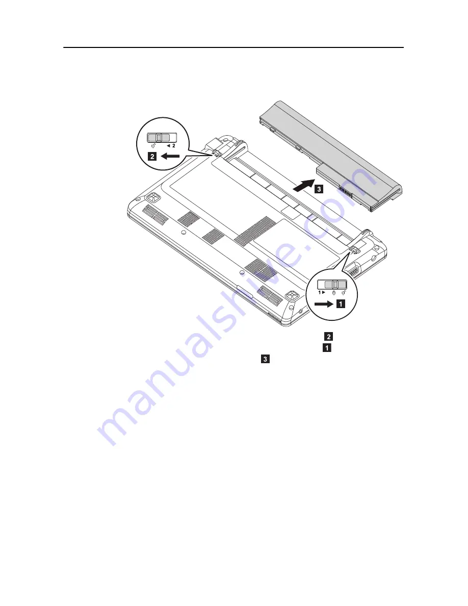
Figure 1: Removal steps of Battery pack

Unlock the battery release slider on the left as shown in 

. Hold the battery 

release slider on the right lever in the unlocked position 

. Remove the battery 

pack in the direction shown by arrow 

When installing:

 Install the battery pack using the slide rails of the slot. Then

make sure that the battery release sliders are set to the locked position.

Содержание IDEAPAD S100

Страница 1: ...IdeaPad S100 Hardware Maintenance Manual ...

Страница 2: ... is delivered pursuant a General Services Administration GSA contract use reproduction or disclosure is subject to restrictions set forth in Contract No GS 35F 05925 2011 Lenovo Note Before using this information and the product it supports be sure to read the general information under Notices on page 74 ...

Страница 3: ...ey Recovery 21 Restore of factory default 21 Using recovery discs 21 Passwords 22 Power on password 22 Supervisor password 22 Power management 22 Screen blank mode 22 Sleep standby mode 22 Hibernation mode 23 Lenovo IdeaPad S100 24 Specifications 24 Status indicators 26 Fn key combinations 28 FRU replacement notices 29 Screw notices 29 Removing and replacing an FRU 30 Battery pack 31 Keyboard 32 B...

Страница 4: ...idelines and safety information required for servicing computers The product specific section includes service reference and product specific parts information Important This manual is intended only for trained servicers who are familiar with Lenovo IdeaPad products Use this manual to troubleshoot problems effectively Before servicing a Lenovo IdeaPad product make sure to read all the information ...

Страница 5: ...ustomer or that makes the machine unsafe Before you start the machine make sure that other service representatives and the customer are not in a hazardous position Place removed covers and other parts in a safe place keeping them away from all personnel while you are servicing the machine Keep your toolcase away from walk areas so that other people will not trip it over Do not wear loose clothing ...

Страница 6: ...is a complete circuit By observing the above rule you may prevent a current from passing through your body When using testers set the controls correctly and use the approved probe leads and accessories for that tester Stand on suitable rubber mats obtained locally if necessary to insulate you from grounds such as metal floor strips and machine frames Observe the special safety precautions when you...

Страница 7: ...any unsafe conditions are present you must determine how serious the apparent hazard could be and whether you can continue without first correcting the problem Consider these conditions and the safety hazards they present Electrical hazards especially primary power primary voltage on the frame can cause serious or fatal electrical shock Explosive hazards such as a damaged CRT face or a bulging cap...

Страница 8: ...g is insulative and retains a charge even when you are wearing a wrist strap Use the black side of a grounded work mat to provide a static free work sur face The mat is especially useful when handling ESD sensitive devices Select a grounding system such as those listed below to provide protection that meets the specific service requirement Attach the ESD ground clip to any frame ground ground brai...

Страница 9: ... nach einem FRU Austausch der Computer wieder angeschlossen wird muß sichergestellt werden daß keine Schrauben Federn oder andere Kleinteile fehlen oder im Gehäuse vergessen wurden Der Computer muß geschüttelt und auf Klappergeräusche geprüft werden Metallteile oder splitter können Kurzschlüsse erzeugen Prima di accendere l elaboratore dopo che é stata effettuata la sostituzione di una FRU accerta...

Страница 10: ...alten Sie darf nicht zerlegt wiederaufgeladen kurzgeschlossen oder Feuer oder Wasser ausgesetzt werden Bei der Entsorgung die örtlichen Bestimmungen für Sondermüll beachten Beim Ersetzen der Bereitschafts oder Systembatterie nur Batterien des Typs verwenden der in der Ersatzteilliste aufgeführt ist Der Einsatz falscher Batterien kann zu Entzündung oder Explosion führen Alcune batterie di riserva c...

Страница 11: ...fgeladen kurzgeschlossen oder Feuer oder Wasser ausgesetzt werden Bei der Entsorgung die örtlichen Bestimmungen für Sondermüll beachten Beim Ersetzen der Batterie nur Batterien des Typs verwenden der in der Ersatzteilliste aufgeführt ist Der Einsatz falscher Batterien kann zu Entzündung oder Explosion führen La batteria contiene piccole quantità di nichel Non smontarla gettarla nel fuoco o nell ac...

Страница 12: ...ieses Typs dürfen nicht aufgeladen zerlegt über 100 C erhitzt oder verbrannt werden Auch darf ihr Inhalt nicht mit Wasser in Verbindung gebracht oder der zur richtigen Polung angebrachte Verbindungsstecker entfernt werden Bei der Entsorgung die örtlichen Bestimmungen für Sondermüll beachten Beim Ersetzen der Batterie nur Batterien des Typs verwenden der in der Ersatzteilliste aufgeführt ist Der Ei...

Страница 13: ...er LCD Bildschirm besteht aus Glas und kann zerbrechen wenn er unsachgemäß behandelt wird oder der Computer auf den Boden fällt Wenn der Bildschirm beschädigt ist und die darin befindliche Flüssigkeit in Kontakt mit Haut und Augen gerät sollten die betroffenen Stellen mindestens 15 Minuten mit Wasser abgespült und bei Beschwerden anschließend ein Arzt aufgesucht werden Nel caso che caso l LCD si d...

Страница 14: ... battery can produce enough current to burn personnel or combustible materials Bien que le voltage des batteries principales soit peu élevé le court circuit ou la mise à la masse d une batterie peut produire suffisamment de courant pour brûler des matériaux combustibles ou causer des brûlures corporelles graves Obwohl Hauptbatterien eine niedrige Spannung haben können sie doch bei Kurzschluß oder ...

Страница 15: ... Safety notice 8 DANGER Before removing any FRU turn off the computer unplug all power cords from electrical outlets remove the battery pack and then disconnect any interconnecting cables Avant de retirer une unité remplaçable en clientèle mettez le système hors tension débranchez tous les cordons d alimentation des socles de prise de courant retirez la batterie et déconnectez tous les cordons d i...

Страница 16: ...rdous radiation exposure O uso de controles ajustes ou desempenho de procedimentos diferentes daqueles aqui especificados pode resultar em perigosa exposição à radiação Pour éviter tout risque d exposition au rayon laser respectez les consignes de réglage et d utilisation des commandes ainsi que les procédures décrites Werden Steuer und Einstellelemente anders als hier festgesetzt verwendet kann g...

Страница 17: ...faisceau de le regarder directement avec des instruments optiques ou de vous exposer au rayon Laserstrahlung bei geöffnetem Gerät Nicht direkt oder über optische Instrumente in den Laserstrahl sehen und den Strahlungsbereich meiden Kinyitáskor lézersugár Ne nézzen bele se szabad szemmel se optikai eszközökkel Kerülje a sugárnyalábbal való érintkezést Aprendo l unità vengono emesse radiazioni laser...

Страница 18: ...y software Use the following strategy to prevent unnecessary expense for replacing and servicing FRUs If you are instructed to replace an FRU but the replacement does not solve the problem reinstall the original FRU before you continue Some computers have both a processor board and a system board If you are instructed to replace either of them and replacing one of them does not solve the problem r...

Страница 19: ...ardous Substances in Electrical and Electronic Equipment Directive 2002 95 EC is a European Union legal requirement affecting the global electronics industry RoHS requirements must be implemented on Lenovo products placed on the market after June 2006 Products on the market before June 2006 are not required to have RoHS compliant parts If the original FRU parts are non compliant replacement parts ...

Страница 20: ...matically shipped by the distribution center at the time of the order Products marketed before June 2006 Products marketed after June 2006 Current or original part Replacement FRU Current or original part Replacement FRU Non RoHS Can be Non RoHS Must be RoHS Must be RoHS Non RoHS Can be RoHS Non RoHS Can sub to RoHS RoHS Must be RoHS ...

Страница 21: ...per maintenance by the customer Notes Only certified trained personnel can service the computer Before replacing any FRU read the entire page on removing and replacing FRUs When you replace FRUs use new nylon coated screws Be extremely careful during such write operations as copying saving or formatting Drives in the computer that you are servicing sequence might have been altered If you select an...

Страница 22: ... the drive or the insertion of a diskette with multiple labels Damaged or bent diskette eject button Fuses blown by attachment of a nonsupported device Forgotten computer password making the computer unusable Sticky keys caused by spilling a liquid onto the keyboard Use of an incorrect AC adapter on laptop products The following symptoms might indicate damage caused by nonwarranted activities Miss...

Страница 23: ...king operational charging To check whether the battery charges properly during operation use a discharged battery pack or a battery pack that has less than 50 of the total power remaining when installed in the computer Perform operational charging If the battery status indicator or icon does not light on remove the battery pack and let it return to room temperature Reinstall the battery pack If th...

Страница 24: ...the battery pack and measure the voltage between battery terminals 1 and 7 See the following figure 3 If the voltage is less than 11 0 V DC the battery pack has been discharged Note Recharging will be continued for at least 3 hours even though the indicator does not light on If the voltage is still less than 11 0 V DC after recharging replace the battery 4 If the voltage is more than 11 0 V DC mea...

Страница 25: ...m see the User Guide for OneKey Rescue System Using recovery discs When you replace a hard disk drive in your computer you are unable to use the pre installed Lenovo OneKey Recovery and OneKey Rescue However you can use the recovery discs that store your backed up data to restore your new hard drive to a previous backup status When you use the recovery discs to boot your computer the system will e...

Страница 26: ...Setup Utility and change the system configuration Attention If the SVP has been forgotten and cannot be made available to the servicer there is no service procedure to reset the password The system board must be replaced for a scheduled fee Power management Note Power management modes are not supported for APM operating system To reduce power consumption the computer has three power management mod...

Страница 27: ...t a few seconds before taking any action to reenter operation mode Hibernation mode In hibernation mode the following occurs The system status RAM VRAM and setup data are stored on the hard disk The system is powered off To cause the computer to enter hibernation mode follow the steps below If you are using the ACPI operating system and have defined one of the fol lowing actions as the event that ...

Страница 28: ... Specifications Feature Description Processor Intel Atom N455 1 66 GHz Intel Atom N570 1 66 GHz Dual Core Intel Atom N435 1 33 GHz South Bridge Chipset Intel NM10 Express Bus architecture 667 MHz FSB PCI PCI Express DMI Graphics Intel integrated graphics Display 10 1 inch glare type white LED backlight 1024 x 600 pixels Memory DDRIII 1333 1GB or 2GB downclocked to be used at 667 MHz One memory slo...

Страница 29: ...AR5B95 Realtek RTL8188CE WLAN Bluetooth combo card Atheros AR5B195 Realtek RTL8188CEBT Integrated camera Fixed focus CMOS 0 3 or 2 0 Mega pixels Battery Lithium ion 24Wh 3 cell or 48Wh 6 cell AC adapter Input 100 240V 50 60Hz AC 3 pin 30W or 40W Output 19V DC Preloaded operating system Windows 7 Starter Windows 7 Home Basic Windows 7 Home Premium MeeGo Free DOS Table 1 Specifications Continued Fea...

Страница 30: ...ators The system status indicators below show the computer status Table 2 Status indicators No Symbol Indicator Indicator status Meaning Power On solid white The computer is powered on Blinking Blinking The computer is in sleep mode Off The computer is powered off ...

Страница 31: ...hite Slow blinking white The battery has between 20 and 80 charge and is still charging When the battery reaches 80 charge the light will stop blinking but charging will continue until the battery is fully charged Off The battery is detached Device access Blinking Data is being read from or written to the hard disk drive or other external storage devices Wireless On Wireless Bluetooth or wireless ...

Страница 32: ...ch to select this notebook or an external display Fn F5 Open the interface for integrated wireless devices settings On Off Fn F6 Enable Disable the touchpad Fn F7 Start Pause playback of Windows Media Player Fn F8 Stop playback of Windows Media Player Fn F9 Skip to the previous track Fn F10 Skip to the next track Fn F11 F12 key Fn PrtSc Activate the system request Fn Pause Activate the break funct...

Страница 33: ...eep the screw kit in your tool bag Always use new screws Use a torque screwdriver if you have one Tighten screws as follows Plastic to plastic Turn an additional 90 after the screw head touches the surface of the plastic part Logic card to plastic Turn an additional 180 after the screw head touches the surface of the logic card Torque driver If you have a torque screwdriver refer to the Torque col...

Страница 34: ...n the figure 7 To put the new FRU in place carry out the removal procedure in reverse and pay attention to any notes pertaining to replacing the parts For information about connecting and arranging internal cables see Locations on page 59 8 When replacing an FRU use the correct screw as shown in the procedures Attention 1 After replacing an FRU do not turn on the computer until you have made sure ...

Страница 35: ...release slider on the left as shown in Hold the battery release slider on the right lever in the unlocked position Remove the battery pack in the direction shown by arrow When installing Install the battery pack using the slide rails of the slot Then make sure that the battery release sliders are set to the locked position ...

Страница 36: ...aintenance Manual 32 Keyboard For access remove this FRU Battery pack on page 31 Figure 2 Removal steps of keyboard Remove the three screws Step Screw quantity Color Torque M2 0 1 7 mm flat head nylon coated 3 Black 1 0 kgfcm 1 1 1 ...

Страница 37: ...igure 3 Removal steps of keyboard continued Lift the keyboard Unlock the PFC connector and then detach the connector in the direction shown by arrow When installing Make sure that the FPC connector is attached firmly and then lock the FPC connector 2 3 4 ...

Страница 38: ...cover For access remove these FRUs in order Battery pack on page 31 Keyboard on page 32 Figure 4 Removal steps of base cover Remove the eight screws Step Screw quantity Color Torque M2 0 6 0 mm flat round head nylon coated 8 Black 1 85 kgfcm 1 1 1 1 1 1 1 1 ...

Страница 39: ...Pad S100 Hardware Maintenance Manual 35 Figure 5 Removal steps of base cover continued Remove the six screws Step Screw quantity Color Torque M2 0 6 0 mm flat round head nylon coated 6 Black 1 85 kgfcm 1 1 1 1 1 1 ...

Страница 40: ...Lenovo IdeaPad S100 Hardware Maintenance Manual 36 Figure 6 Removal steps of base cover continued Lift the base cover as shown by the arrow ...

Страница 41: ... need to be peeled off from the old base cover and put on the new base cover Windows license label COA Chinese service information label Homologation label US CA Taiwan Israel label Rating label Refer to the illustration below for the location of each label For some models you also need to apply one or two FCC labels Check the old base cover if it has one or two FCC labels find duplicates of them ...

Страница 42: ...e FRUs in order Battery pack on page 31 Keyboard on page 32 Base cover on page 34 Figure 7 Procedure to remove the DIMM Release the latches on both edges of the socket at the same time in the direction shown by arrows and then unplug the DIMM in the direction shown by arrow 1 1 2 ...

Страница 43: ...When installing Make sure that the HDD connector is attached firmly Attention Do not drop the hard disk drive or apply any physical shock to it The hard disk drive is sensitive to physical shock Improper handling can cause damage and permanent loss of data Before removing the drive suggest to the customer that they should back up all the information on it if possible Never remove the drive while t...

Страница 44: ... Manual 40 Figure 9 Removal steps of hard disk drive continued Remove the two side screws and then detach the hard disk drive from its bracket Step Screw quantity Color Torque M3 0 3 0 mm flat round head nylon coated 2 Black 2 85 kgfcm 2 1 1 ...

Страница 45: ...ack on page 31 Keyboard on page 32 Base cover on page 34 Figure 10 Removal steps of USB port Remove one screw Unlock the USB connector and then detach the connector in the direction shown by arrow Remove USB port Step Screw quantity Color Torque M2 0 3 0 mm flat round head nylon coated 1 Black 1 35 kgfcm 1 3 ...

Страница 46: ...1 Removal steps of thermal module Remove the four screws Detach the connector in the direction shown by arrow Lift and remove the thermal module in the direction shown by arrow When installing Make sure that the thermal module connector is attached firmly to the system board Step Screw quantity Color Torque M2 0 3 0 mm flat round head nylon coated 4 Black 1 35 kgfcm 3 2 1 1 1 1 ...

Страница 47: ... pack on page 31 Keyboard on page 32 Base cover on page 34 Figure 12 Removal steps of PCI Express Mini Card for wireless LAN Remove one screw Unplug the two cables Then remove the PCI Express Mini Card in the direction shown by the arrow Step Screw quantity Color Torque M2 0 6 0 mm flat round head nylon coated 1 Black 1 85 kgfcm 1 3 2 ...

Страница 48: ...se FRUs in order Battery pack on page 31 Keyboard on page 32 Base cover on page 34 Figure 13 Removal steps of RJ 45 connector Detach the connector in the direction shown by arrow Lift the RJ 45 connector as shown by arrow When installing Make sure that the connector is attached firmly 1 2 ...

Страница 49: ... in order Battery pack on page 31 Keyboard on page 32 Base cover on page 34 Figure 14 Removal steps of power connector Detach the connector in the direction shown by arrow Lift the power connector in the direction shown by arrow When installing Make sure that the connector is attached firmly 1 2 ...

Страница 50: ...ortant notices for handling the system board When handling the system board bear the following in mind Be careful not to drop the system board on a bench top that has a hard surface such as metal wood or composite Avoid rough handling of any kind Take care not to drop or stack the system board during the whole of the procedure If you put a system board down make sure to put it only on a padded sur...

Страница 51: ...al 47 Figure 16 Removal steps of system board continued Detach the six connectors in the directions shown by arrows Remove the system board in the direction shown by arrow When installing Make sure that all connectors are attached firmly 3 2 2 2 2 ...

Страница 52: ... on page 39 PCI Express Mini Card for wireless LAN on page 43 System board on page 46 Figure 17 Removal steps of speakers Remove the two side screws for each speaker Release the speaker cables from the cable guides and then remove the speakers in the direction shown by arrows Step Screw quantity Color Torque M2 0 3 0 mm flat round head nylon coated 4 Black 1 35 kgfcm 1 1 2 1 1 2 ...

Страница 53: ...e 32 Base cover on page 34 Hard disk drive on page 39 PCI Express Mini Card for wireless LAN on page 43 System board on page 46 Figure 18 Removal steps of Touch pad bracket Remove the two screws Remove the metal cover in the direction shown by arrow Step Screw quantity Color Torque M2 0 3 0 mm flat round head nylon coated 2 Black 1 35 kgfcm 1 1 2 ...

Страница 54: ...IdeaPad S100 Hardware Maintenance Manual 50 Figure 19 Removal steps of Touch pad bracket continued Use a screwdriver to push and unlock the tabs Remove the touch pad bracket in the direction shown by arrow 4 3 ...

Страница 55: ...D unit For access remove these FRUs in order Battery pack on page 31 Keyboard on page 32 Base cover on page 34 Figure 20 Procedure to remove the LCD unit Step Screws quantity Color Torque M2 0 5 0 mm flat round head nylon coated 4 Black 1 85 kgfcm 1 2 1 2 ...

Страница 56: ...nce Manual 52 Figure 21 Procedure to remove the LCD unit continued Remove the six back screws Detach the three connectors in the direction shown by arrow Remove the LCD unit When installing Make sure that all connectors are attached firmly ...

Страница 57: ...tery pack on page 31 Keyboard on page 32 Base cover on page 34 LCD unit on page 51 Figure 22 Removal steps of LCD front bezel Remove the two screws Remove the LCD front bezel in the direction shown by arrows Step Screw quantity Color Torque M2 0 3 0 mm flat round head nylon coated 2 Black 1 35 kgfcm 1 1 2 2 2 ...

Страница 58: ... 32 Base cover on page 34 LCD unit on page 51 LCD front bezel on page 53 Figure 23 Removal steps of LCD panel Remove the four screws Detach the connector under the LCD panel and then remove the LCD panel in the direction shown by arrow Step Screw quantity Color Torque M2 0 3 0 mm flat round head nylon coated 4 Black 1 35 kgfcm 1 1 1 1 2 3 ...

Страница 59: ... page 53 LCD panel on page 54 Figure 24 Removal steps of integrated camera The integrated camera is attached to the top center of the LCD cover Lift the integrated camera in the direction shown by arrow Detach the connector in the direction shown by arrow When installing Attach the integrated camera to the top center of the LCD cover and ajust the its placement to make sure the connector is attach...

Страница 60: ...rd on page 32 Base cover on page 34 LCD unit on page 51 LCD front bezel on page 53 LCD panel on page 54 Figure 25 Removal steps of hinges Remove the six screws Lift and remove the hinges in the direction shown by arrows Step Screw quantity Color Torque M2 0 3 0 mm flat round head nylon coated 6 Black 1 35 kgfcm 1 1 1 2 1 1 1 2 ...

Страница 61: ...e 53 LCD panel on page 54 Hinges on page 56 Figure 26 Removal steps of power button board The power button board is attached to the left side of the LCD cover Detach the connector in the direction shown by arrow Remove the power button board in the direction shown by arrow When installing Attach the power button board to the left side of the LCD cover and adjust its placement to make sure it is at...

Страница 62: ...zel on page 53 LCD panel on page 54 Hinges on page 56 Power button board on page 57 Figure 27 Removal steps of antenna kit The antenna modules are attached to the left and right sides of the LCD cover Remove the antenna modules in the direction shown by arrows When installing Stick the antenna modules to the sides of the LCD cover and adjust their placement to make sure they are attached firmly 1 ...

Страница 63: ...egrated camera Use the camera for video communication Built in microphone The built in microphone with noise reduction can be used for video conferencing voice narration or simple audio recordings Computer display The computer display with LED backlight provides brilliant visual output QS Quick Start button When the computer is powered off press this button to start Lenovo Quick Start OneKey Rescu...

Страница 64: ...Wireless module antennas The built in antennas ensure optimal reception of wireless radio AC power adapter jack Connect the AC adapter here VGA port Connects to external display devices Fan louvers Dissipate internal heat USB port Connects to USB devices Combo audio jack Connects to headsets or headphones Attention Listening to music at high volume over extended periods of time may damage your hea...

Страница 65: ...anual 61 Right side view Front view USB port Connects to USB devices RJ 45 port This port connects the computer to an Ethernet network Lanyard hole Used for attaching a lanyard not supplied Memory card slot Insert memory cards not supplied here ...

Страница 66: ...ttery latch manual The manual battery latch is used to keep the battery pack secured in place Battery pack Battery latch spring loaded The spring loaded battery latch keeps the battery pack secured in place Speakers The stereo speakers provide rich and powerful sound ...

Страница 67: ...ion presents the following service parts Overall on page 64 LCD FRUs on page 68 Keyboard on page 70 Miscellaneous parts on page 71 AC adapters on page 72 Power cords on page 72 Note Each FRU is available for all types or models unless specific types or models are specified ...

Страница 68: ...Lenovo IdeaPad S100 Hardware Maintenance Manual 64 Overall ...

Страница 69: ...d half size 20 002578 4 Realtek RTL8188CE Wi Fi PCIE mini card half size 20 002579 4 Atheros AR5B195 Wi Fi BT combo PCIE mini card half size 20 002580 4 Realtek 8188CEBT Wi Fi BT combo PCIE mini card half size 20 002581 5 System board assembly with Intel Atom Pineview N455 1 66GHz CPU 11 013590 5 System board assembly with Intel Atom Pineview N570 1 66GHz CPU 11 013591 5 System board assembly with...

Страница 70: ...B 5 400rpm 16 004642 10 SATA Hard disk drive assembly 500GB 5 400rpm 16 004846 10 SATA Hard disk drive assembly 500GB 5 400rpm 16 004189 10 SATA Hard disk drive assembly 500GB 5 400rpm 16 004058 11 1GB DDR3 1333 SDRAM SO DIMM card 11 011936 11 1GB DDR3 1333 SDRAM SO DIMM card 11 012767 11 1GB DDR3 1333 SDRAM SO DIMM card 11 012634 11 1GB DDR3 1333 SDRAM SO DIMM card 11 012975 11 1GB DDR3 1333 SDRA...

Страница 71: ...12 Thermal module for N570 31 050126 13 Battery pack Li ion 3 cell 2 2Ah 121 001129 13 Battery pack Li ion 3 cell 2 2Ah 121 001125 13 Battery pack Li ion 6 cell 4 4Ah 121 001127 13 Battery pack Li ion 6 cell 4 4Ah 121 001123 Table 4 Parts list Overall Continued No FRU FRU No or Lenovo P N ...

Страница 72: ...Lenovo IdeaPad S100 Hardware Maintenance Manual 68 LCD FRUs ...

Страница 73: ... 1 in WSVGA Glare 18 004990 2 LCD panel 10 1 in WSVGA Glare 18 004991 3 Left antenna for Wi Fi WiMAX 31 050132 3 Right antenna for Wi Fi WiMAX 31 050133 4 Power button 11 013589 5 Left hinge 31 050137 5 Right hinge 31 050140 6 LCD cover black 31 050145 6 LCD cover blue 31 050631 6 LCD cover red 31 050632 6 LCD cover white 31 050774 7 S100 LVDS CABLE 31 050131 8 Power cable 31 050127 9 Integrated c...

Страница 74: ...5 010988 25 010025 25 009915 German 25 010923 25 010989 25 010024 25 009914 Greek U S English and Greek layout 25 010928 25 010994 25 010019 25 009908 Hebrew 25 010929 25 010995 25 010018 25 009907 Hungarian 25 010930 25 010996 25 010017 25 009906 Icelandic 25 010933 25 010972 25 010014 25 009903 Italian 25 010912 25 010978 25 010035 25 010072 Japanese 25 010940 25 010969 25 009921 25 009920 Korea...

Страница 75: ...0914 25 010980 25 010033 25 010070 U K English 25 010938 25 010967 25 009926 25 009925 U S English 25 010939 25 010968 25 009924 25 009923 U S English International with a Euro symbol 25 010937 25 010966 25 010010 25 009899 Table 7 Parts list Miscellaneous parts FRU FRU No or Lenovo P N a HDD bracket 31 050142 b USB cable 31 050128 c DC in cable 31 050151 d Touch pad bracket 31 050144 e RJ 45 conn...

Страница 76: ...28 Australia New Zealand 145 000589 145 000557 145 000532 Brazil 145 000596 145 000564 145 000527 China P R C other than Hong Kong S A R 145 000602 145 000600 145 000568 145 000538 European countries 145 000585 145 000553 145 000525 Denmark 145 000598 145 000566 145 000534 India 145 000592 145 000560 145 000536 Israel 145 000595 145 000563 145 000526 Italy 145 000591 145 000559 145 000535 Japan 14...

Страница 77: ...deaPad S100 Hardware Maintenance Manual 73 Canada U S 145 000594 145 000562 145 000537 U K China Hong Kong S A R 145 000593 145 000561 145 000605 Table 9 Parts list 3 pin power cords Continued Region 3 Pin P N ...

Страница 78: ...and or changes in the product s and or the program s described in this publication at any time without notice The products described in this document are not intended for use in implantation or other life support applications where malfunction may result in injury or death to persons The information contained in this document does not affect or change Lenovo product specifications or warranties No...

Страница 79: ...ks or registered trademarks of Lenovo in the United States other countries or both Lenovo IdeaPad OneKey Microsoft and Windows are trademarks of Microsoft Corporation in the United States other countries or both Other company products or service names may be trademarks or service marks of others ...

Отзывы: