To replace a microprocessor, perform the following steps:
1. Make sure you know which microprocessor is to be replaced. You can identify the failed microprocessor
by either checking in XClarity Administrator or the POST error log on the IMM console.
2. Shut down the node by following the hypervisor specific Node Shutdown procedure described in the
Nutanix Hardware Replacement Documentation.
3. Power off the node, disconnect all cables, and remove the node from the rack.
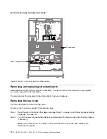
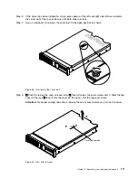
4. Remove the top cover as described in “Removing the top cover” on page 116.
5. Remove the air baffle as described in “Removing the air baffle” on page 119.
6. Replace the microprocessor as described in “Replacing a microprocessor and heat sink” on page 213.
7. Replace the air baffle as described in “Replacing the air baffle” on page 120.
8. Replace the top cover as described in “Replacing the top cover” on page 118.
9. Return the node to the rack, reconnect the cables as necessary and power on the node.
10. Start the node by following the hypervisor specific Node Start procedure described in the Nutanix
Hardware Replacement Documentation.
11. Verify that the microprocessor has been successfully replaced by checking the following:
• Orange warning light on the node front panel is extinguished.
• Post error log in the IMM
Replacing the system board
Lenovo support may instruct you that the system board needs to be replaced. This is a level 2 CRU and
should be performed by a trained Lenovo field representative.
To replace the system board, perform the following steps:
1. Shut down the node by following the hypervisor specific Node Shutdown procedure described in the
Nutanix Hardware Replacement Documentation.
2. Power off the node, disconnect all cables to the node, and remove the node from the rack as necessary.
3. Remove the top cover as described in “Removing the top cover” on page 116.
4. Remove the system board as described in “Removing the system board” on page 223.
5. Replace the system board as described in “Replacing the system board” on page 226.
6. Replace the top cover as described in “Replacing the top cover” on page 118.
7. Return the node to the rack and reconnect the cables as necessary. Power on the node.
8. Verify that the system board has been successfully replaced by checking the following:
• Orange warning light on the node front panel is extinguished.
• System boots successfully with no POST errors or other errors.
9. Stop the startup process at the main IMM menu screen to configure the new system board as a Lenovo
Converged HX appliance using the following procedures in Chapter 2 “Configuration information and
instructions” on page 33.
• Update the server VPD data
• Legacy boot mode
• Disable option ROMs
• BIOS optimization settings
• Modify boot options
10. Save the settings and boot into the hypervisor.
11. Start the node by following the hypervisor specific Node Start procedure described in the Nutanix
Hardware Replacement Documentation.
110
HX3510-G, HX5510, HX5510-C, HX7510 Installation and Service Guide
Содержание HX3510-G
Страница 1: ...HX3510 G HX5510 HX5510 C HX7510 Installation and Service Guide Machine Type 8695 ...
Страница 6: ...iv HX3510 G HX5510 HX5510 C HX7510 Installation and Service Guide ...
Страница 62: ...50 HX3510 G HX5510 HX5510 C HX7510 Installation and Service Guide ...
Страница 102: ...90 HX3510 G HX5510 HX5510 C HX7510 Installation and Service Guide ...
Страница 112: ...100 HX3510 G HX5510 HX5510 C HX7510 Installation and Service Guide ...
Страница 1222: ...1210 HX3510 G HX5510 HX5510 C HX7510 Installation and Service Guide ...
Страница 1229: ...People s Republic of China Class A electronic emission statement Taiwan Class A compliance statement Appendix E Notices 1217 ...
Страница 1230: ...Taiwan BSMI RoHS declaration 1218 HX3510 G HX5510 HX5510 C HX7510 Installation and Service Guide ...
Страница 1238: ...1226 HX3510 G HX5510 HX5510 C HX7510 Installation and Service Guide ...
Страница 1239: ......
Страница 1240: ......

