


Lenovo E41-10/E41-15 Hardware Maintenance Manual
60
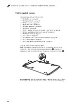
1140 Integrated camera
For access, remove these FRUs in order:
• “1010 Keyboard” on page 34
• “1020 Optical drive” on page 36
• “1030 Base cover” on page 37
• “1040 Battery pack” on page 39
• “1050 Hard disk drive” on page 41
• “1060 DIMM” on page 43
• “1070 PCI Express Mini Card for wireless LAN/WAN” on page 44
• “1080 Fan assembly and Heat Sink assembly” on page 47
• “1090 System board” on page 49
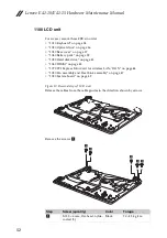
• “1100 LCD unit” on page 52
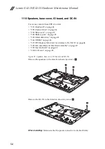
• “1110 Speakers, base cover, IO board, and DC-IN” on page 54
• “1120 LCD front bezel” on page 57
• “1130 LCD panel, LCD cable and hinges” on page 58
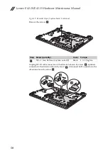
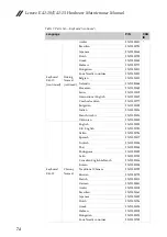
Figure 14. Removal steps of integrated camera
Note:
The integrated camera is stuck on the top center of the LCD cover.
Unplug the connector in the direction shown by arrow
, remove the
integrated camera from the LCD cover in the direction shown by arrow
.
When installing:
Stick the integrated camera to the top center of the LCD cover
and adjust the placement of it to make sure the connector is attached firmly.
a
b
a
b