A video of this procedure is available at YouTube:
https://www.youtube.com/playlist?list=PLYV5R7hVcs-
.
Step 1. If a drive backplane is installed in the compute note that is incompatible with the interposer card,
remove it (see
“Remove the 2.5-inch drive backplane” on page 57
for instructions).
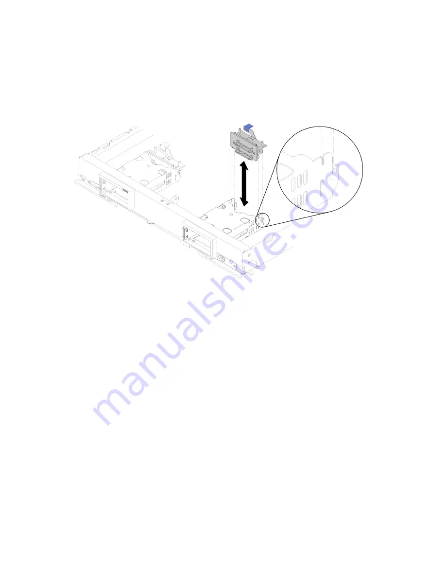
Step 2. If you are installing both the interposer card and drive backplane, first install the drive backplane in
the compute node (see
“Install a 2.5-inch drive backplane” on page 34
for instructions). The drive
backplane goes in the rear alignment slots on the drive cage.
Figure 26. Drive backplane installation with backplane alignment slots
Step 3. Touch the static-protective package that contains the interposer card to an
unpainted
metal
surface on any grounded rack component; then, remove the interposer card from the package.
Step 4. Locate the interposer card connector on the top of drive backplane.
Step 5. Orient the connector on the interposer card with the connector on drive backplane.
50
ThinkSystem SN850 Compute Node Setup Guide
Содержание 7X15
Страница 1: ...ThinkSystem SN850 Compute Node Setup Guide Machine Type 7X15 ...
Страница 4: ...ii ThinkSystem SN850 Compute Node Setup Guide ...
Страница 8: ...vi ThinkSystem SN850 Compute Node Setup Guide ...
Страница 22: ...14 ThinkSystem SN850 Compute Node Setup Guide ...
Страница 34: ...26 ThinkSystem SN850 Compute Node Setup Guide ...
Страница 92: ...84 ThinkSystem SN850 Compute Node Setup Guide ...
Страница 100: ...92 ThinkSystem SN850 Compute Node Setup Guide ...
Страница 103: ......
Страница 104: ...Part Number SP47A10189 Printed in China 1P P N SP47A10189 1PSP47A10189 ...


