background image

Page 30

506518−01

System Operation

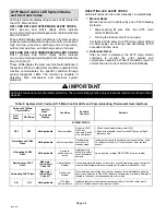
IMPORTANT

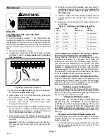
Some scroll compressor have internal vacuum protector
that will unload scrolls when suction pressure goes
below 20 psig. A hissing sound will be heard when the
compressor is running unloaded. Protector will reset
when low pressure in system is raised above 40 psig. DO
NOT REPLACE COMPRESSOR.

The A175 main control provides the following system
functions:

S

Compressor anti−short−cycle delay.

S

High and low pressure switches

S

Ambient and Discharge Line Temperatures Monitoring
and Protection.

S

Five strikes lockout safety function for High/Low
Pressure Switches and High Discharge Temperature.

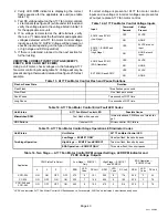
COMPRESSOR ANTI−SHORT CYCLE DELAY

The A175 main control protects the compressor from:

S

Short cycling (five minutes) when there is initial power
up

S

Interruption in power to the unit

S

High or low pressure switch or discharge line sensor
trips

S

Delay after Y1 demand is removed.

Resetting Anti−Short Cycle Delay

The 

E33

 pins on the A175 main control can be jumpered

between 1 to 2 seconds to reset the anti−short cycle delay
sequence.

HIGH AND LOW PRESSURE SWITCHES

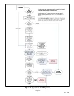
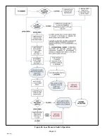
The unit’s reset pressure switches LO PS (S4) and HI PS
(S87) are factory−wired into the A175 main control on the
LO−PS and HI−PS terminals, there locations are illustrated
on page 3. Sequence of operations for both pressure
switches are provided in figures 19 and 20.

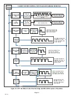
HIGH DISCHARGE LINE TEMPERATURE 

SENSOR

(RT28)

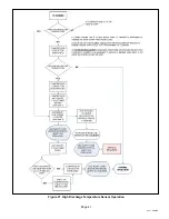
The high discharge line temperature sensor location is
illustrated on page 3. This sensor’s sequence of
operations is provided in figure 21.

High Discharge Line Sensor Open/Shorted Event

Condition

Discharge sensor open / short fault is ignored during initial
90−seconds of compressor run time. After that, if discharge
temperature sensor is detected open or short, the control
will de−energize all the outputs and anti−short cycle timer is
started. Discharge sensor faulty alert LED code will be
displayed.

OUTDOOR AMBIENT TEMPERATURE (RT13)

If the outdoor ambient temperature sensor detected a
open, or out of range −40ºF to +140ºF (−40ºC to 60ºC) then
LED alert codes are displayed, however cooling operation
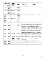
will continue. See table 9 for LED alert codes for the
ambient sensor. This sensor’s location is illustrated in page
3.

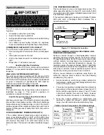
COIL TEMPERATURE SENSOR

This model does not use a coil temperature sensor. The
cable assembly attached to the A175 main control’s E30
connection has a 10K resister installed between pins 5 and
6 as illustrated in figure 17.

If the resistor is damage or missing, a Coil Sensor Problem
LED alert code is displayed which indicates this a
open/shorted circuit.

10K resistor

High Discharge Line

Temperature Sensor

Ambient Air

Temperature Sensor

Figure 17. 10k Resistor Location

TESTING AMBIENT AND HIGH DISCHARGE LINE
TEMPERATURE SENSORS

Sensors connect through a field-replaceable harness
assembly that plugs directly into the A175 main controll.
Through these sensors, the A175 main control can monitor
outdoor ambient and discharge line temperature fault
conditions. As the detected temperature changes, the
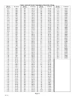
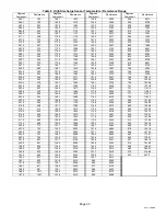
resistance across the sensor changes. Tables 7 and 8 lists
how the resistance varies as the temperature changes for
both type of sensors. Sensor resistance values can be
checked by ohming across pins shown in table 6.

When a sensor indicates a resistance value that is not
within the range as listed in table 6, then the following
condition may be present:

S

Sensor detects an out−of−range outdoor ambient air
temperature condition and will display LED alert code
on the A175 main control.

S

The sensor is operating normally when the ambient air
temperature at the sensor is below or above the A175
main control’s expected ohm values. The A175 main
controll will indicate the sensor as faulty, however
under this scenario, the sensor is not actually faulty.

S

Once the outdoor ambient air temperature has
returned to within the sensor’s normal operating
range, the LED alert code will automatically stop.

Table 6. Sensor Temperature / Resistance Range

Sensor

Temperature
Range °F (°C)

Resistance
values range
(ohms)

Pins/
Wire
Color

Outdoor
(Ambient)

−40ºF to 140ºF
(−40ºC to 60ºC)

280,000 to 3750

3 and 4
(Black)

Discharge

−35ºF to 310ºF

(−37ºC to 154ºC)

41,000 to 103

1 and 2
(Yellow)

Note: Sensor resistance decreases as sensed temperature increases
(see tables 7 and 8.

Содержание XC21

Страница 1: ...igned for use in expansion valve systems only An indoor expansion valve approved for use with HFC 410A refrigerant must be ordered separately and installed prior to operating the system INSTALLATION INSTRUCTIONS Dave Lennox Signature Collection XC21 System AIR CONDITIONER 506518 01 06 10 Supersedes 05 10 RETAIN THESE INSTRUCTIONS FOR FUTURE REFERENCE TABLE OF CONTENTS General 1 Shipping and Packin...

Страница 2: ...S VIEW DISCHARGE AIR 4 5 8 117 BASE WITH ELONGATED LEGS 16 7 8 429 8 3 4 222 26 7 8 683 3 3 4 95 30 3 4 781 3 1 8 79 SUCTION LINE INLET UNIT SUPPORT FEET Model Number Identification C 21 XXX Unit Type C Air Conditioner Series Nominal Cooling Capacity 024 2 tons 036 3 tons 048 4 tons 060 5 tons Minor Revision Number 230 Voltage 230 208 230V 1ph 60hz Refrigerant Type X R 410A X 05 ...

Страница 3: ...RATURE SENSOR S87 LOW PRESSURE SWITCH S4 HIGH PRESSURE SWITCH S40 CRANKCASE THERMOSTAT COMPRESSOR HARNESS FIELD CONNECTION FOR LIQUID LINE GROUND LUG HIGH VOLTAGE FIELD CONNECTIONS CONTACTOR 1 POLE K1 A175 MAIN CONTROL CAPACITOR C12 A177 FAN MOTOR CONTROL WIRE TIE RT13 OUTDOOR AMBIENT TEMPERATURE SENSOR FAN MOTOR SURGE PROTECTION SECOND GROUND LUG FOR SOURCESOURCE Figure 1 Plumbing Switches and Se...

Страница 4: ...oning components ensure the fasteners are appropriately tightened Table 1 shows torque values for fasteners IMPORTANT Only use Allen wrenches of sufficient hardness 50Rc Rockwell Harness Scale minimum Fully insert the wrench into the valve stem recess Service valve stems are factory torqued from 9 ft lbs for small valves to 25 ft lbs for large valves to prevent refrigerant loss during shipping and...

Страница 5: ...rvice port 3 When testing is completed replace service port cap and tighten as fol lows 1 2 3 4 5 6 7 8 9 10 11 12 1 6 TURN Operating Angle Type Service Valve 1 Remove stem cap with an appropriately sized wrench 2 Use a service wrench with a hex head extension 3 16 for liquid line valve sizes and 5 16 for vapor line valve sizes to back the stem out counterclockwise as far as it will go Operating B...

Страница 6: ...tops pumping when the pressure ratio meets a certain value or when the suction pressure is as high as 20 psig Compressor suction pressures should never be allowed to go into a vacuum Prolonged operation at low suction pressures will result in overheating of the scrolls and permanent damage to the scroll tips drive bearings and internal seals Once the compressor can not pump down to a lower pressur...

Страница 7: ...he unit directly outside a window Glass has a very high level of sound transmission For proper placement of unit in relation to a window see the provided illustration in figure 5 detail A PLACING UNIT ON SLAB When installing unit at grade level the top of the slab should be high enough above grade so that water from higher ground will not collect around the unit The slab should have a slope tolera...

Страница 8: ... unit above a load bearing wall or area of the roof that can adequately support the unit Consult local codes for rooftop applications NOTICE Roof Damage This system contains both refrigerant and oil Some rubber roofing material may absorbed oil and cause the rubber to swell when it comes into contact with oil The rubber will then bubble and could cause leaks Protect the roof surface to avoid expos...

Страница 9: ...et Extenders Stabilizing Unit on Uneven Surfaces WOOD OR PLASTIC SLAB NO PLASTIC ANCHOR HOLE DRILL 1 8 SAME FASTENERS AS SLAB SIDE MOUNTING IMPORTANT To help stabilize an outdoor unit some installations may require strapping the unit to the pad using brackets and anchors commonly available in the marketplace DETAIL C DETAIL D 2 50 8MM SCH 40 MALE THREADED ADAPTER Use additional 2 SCH 40 male threa...

Страница 10: ...parallel with the unit as illustrated in detail D with the screw side as close to the unit as possible Then in a continuous motion 1 Slightly rotate and guide the lip of top tab inward as illustrated in detail A and C then upward into the top slot of the hinge corner post 2 Rotate panel to vertical to fully engage all tabs 3 Holding the panel s hinged side firmly in place close the right hand side...

Страница 11: ...1 8 adapter NOTE When installing refrigerant lines longer than 50 feet see the Lennox Refrigerant Piping Design and Fabrication Guidelines CORP 9351 L9 or contact Lennox Technical Support Product Applications for assistance To obtain the correct information from Lennox be sure to communicate the following information S Model XC21 and size of unit e g 036 S Line set diameters for the unit being ins...

Страница 12: ...hould be used if line set is to be installed on exterior of outside wall PVC PIPE FIBERGLASS INSULATION CAULK OUTSIDE WALL VAPOR LINE WRAPPED WITH ARMAFLEX LIQUID LINE OUTSIDE WALL LIQUID LINE VAPOR LINE WOOD BLOCK BETWEEN STUDS STRAP WOOD BLOCK STRAP SLEEVE WIRE TIE WIRE TIE WIRE TIE INSIDE WALL REFRIGERANT LINE SET INSTALLING VERTICAL RUNS NEW CONSTRUCTION SHOWN INSTALLATION LINE SET NOTE Insula...

Страница 13: ...e valve stem port connection on the vapor service valve NOTE The fixed orifice or check expansion valve metering device at the indoor unit will allow low pressure nitrogen to flow through the system NITROGEN HIGH LOW USE REGULATOR TO FLOW NITROGEN AT 1 TO 2 PSIG BRAZE LINE SET INSTALL SERVICE PORT CAPS ONLY Braze the liquid line to the liquid line service valve Turn off nitrogen flow After all con...

Страница 14: ...ded fitting to temporary reconnect the liquid line to the indoor unit s liquid line orifice housing LOW HIGH EXISTING INDOOR UNIT GAUGE MANIFOLD INVERTED HCFC 22 CYLINDER CONTAINS CLEAN HCFC 22 TO BE USED FOR FLUSHING LIQUID LINE SERVICE VALVE INLET DISCHARGE TANK RETURN CLOSED OPENED RECOVERY CYLINDER RECOVERY MACHINE NEW OUTDOOR UNIT VAPOR LINE SERVICE VALVE VAPOR LIQUID 1 A Inverted HCFC 22 cyl...

Страница 15: ...fitting that temporary reconnected the liquid line to the indoor unit s distributor assembly B Install one of the provided Teflon rings around the stubbed end of the check expansion valve and lightly lubricate the connector threads and expose surface of the Teflon ring with refrigerant oil C Attach the stubbed end of the check expansion valve to the liquid line orifice housing Finger tighten and u...

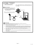
Страница 16: ... existing traps Polyol ester POE oils are used in Lennox units charged with HFC 410A refrigerant Residual mineral oil can act as an insulator preventing proper heat transfer It can also clog the expansion device and reduce the system performance and capacity Failure to properly flush the system per the instructions below will void the warranty Leak Testing the System IMPORTANT Leak detector must b...

Страница 17: ...nder of dry nitrogen with a pressure regulating valve to the center port of the manifold gauge set D Adjust dry nitrogen pressure to 150 psig 1034 kPa Open the valve on the high side of the manifold gauge set in order to pressurize the line set and the indoor unit E After a few minutes open one of the service valve ports and verify that the refrigerant added to the system earlier is measurable wit...

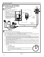
Страница 18: ...olute pressure does not rise above 500 microns 29 9 inches of mercury within a 20 minute period after shutting off the vacuum pump and closing the manifold gauge valves F When the absolute pressure requirement above has been met disconnect the manifold hose from the vacuum pump and connect it to an upright cylinder of HFC 410A refrigerant Open the manifold gauge valve 1 to 2 psig in order to relea...

Страница 19: ...to the unit nameplate for minimum circuit ampacity and maximum fuse or circuit breaker HACR per NEC Install power wiring and properly sized disconnect switch NOTE Units are approved for use only with copper conductors Ground unit at disconnect switch or to an earth ground SIZE CIRCUIT AND INSTALL DISCONNECT SWITCH 1 NOTE 24VAC Class II circuit connections are made in the control panel Install room...

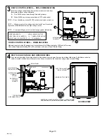
Страница 20: ...VAC control wire connections to A175 main control ROUTE CONTROL WIRES COMMUNICATING Maximum length of wiring 18 gauge for all connections on the RSBus is limited to 1500 feet 457 meters Color coded temperature rating 95ºF 35ºC minimum solid core Class II Rated Wiring Any excess high voltage field wiring should be trimmed and secured away from any low voltage field wiring To facilitate a conduit a ...

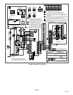
Страница 21: ...Page 21 XC21 SERIES Figure 8 Typical XC21 Wiring ...

Страница 22: ...basic and precision dehumidification ECM fan motor 24VDC output connection 2 E28 FAN C ECM common connection for ECM fan E30 Six position square pin header E30 provides connections for the temperature sensors DIS YELLOW PINS 5 and 6 DIS 5 Discharge line temperature sensor supply DIS 6 Discharge line temperature sensor return Range is 35ºF to 310ºF Sensor is clipped on a 1 2 copper tube AMB BLACK P...

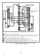
Страница 23: ...ComfortSense 7000 Thermostats Catalog Y0349 or Y2081 On board link Low voltage thermostat wiring Flat metal jumper 4 3 4 A175 main control comes from factory with metal jumpers across W1 W2 and W3 For one stage electric heat do not remove metal jumpers A175 main control comes from factory with metal jumpers across W1 W2 and W3 For two stage electric heat remove metal jumper between W1 to W2 and co...

Страница 24: ...tSense 7000 Y2081 Outdoor sensor for outdoor temperature display Optional 1 2 4 5 Cut Furnace Control on board link W915 clippable wire for two stage operation 3 3 Cut loop jumper clippable wire for Humiditrol application This will slow the outdoor unit s blower motor to 250 RPM A wire must be installed between the DS terminals on the air handler and outdoor unit controls Cut on board link clippab...

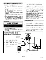
Страница 25: ...e If not do not start the equipment until you have consulted with the power company and the voltage condition has been corrected 6 Set the thermostat for a cooling demand Turn on power to the indoor indoor unit and close the outdoor unit disconnect switch to start the unit 7 Recheck voltage while the unit is running Power must be within range shown on the nameplate 8 Check system for sufficient re...

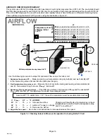
Страница 26: ...0 Temperature of air entering indoor coil ºF INDOOR COIL DRY BULB DRY BULB WET BULB B TDrop 19º A Dry bulb Wet bulb ºF A 72º B 64º C 53º air flow air flow All temperatures are expressed in ºF 1 Determine the desired DT Measure entering air temperature using dry bulb A and wet bulb B DT is the intersecting value of A and B in the table see triangle 2 Find temperature drop across coil Measure the co...

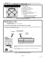
Страница 27: ...just from 15 feet 4 6 m line set 3 8 9 5 mm 3 ounce per 5 85 g per 1 5 m If line length is greater than 15 ft 4 6 m add this amount If line length is less than 15 ft 4 6 m subtract this amount Refrigerant Charge per Line Set Length CHARGING METHOD NOTE Insulate liquid line when it is routed through areas where the surrounding ambient temperature could become higher than the temperature of the liqu...

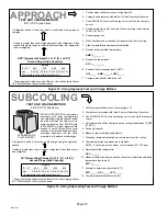
Страница 28: ... necessary with lower temperatures Use cardboard or plastic sheet to restrict the airflow through the outdoor coil to achieve pressures from 325 375 psig 2240 2585kPa Higher pressures are needed to check charge Block equal sections of air intake panels and move coverings sideways until the liquid pressure is in the above noted ranges If value is greater than shown remove refrigerant if less than s...

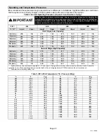
Страница 29: ...115 46 1 426 152 436 154 459 152 468 146 Second Stage High Capacity 65 18 3 213 138 214 137 217 124 238 130 75 23 9 245 142 247 140 251 133 276 133 85 29 4 285 142 288 141 289 138 317 135 95 35 0 329 144 330 143 336 141 368 139 105 40 6 376 147 384 145 385 144 420 141 115 46 1 432 151 445 148 437 146 478 143 Typical pressures only expressed in psig liquid 10 and vapor 5 psig indoor match up indoor...

Страница 30: ...ºC to 60ºC then LED alert codes are displayed however cooling operation will continue See table 9 for LED alert codes for the ambient sensor This sensor s location is illustrated in page 3 COIL TEMPERATURE SENSOR This model does not use a coil temperature sensor The cable assembly attached to the A175 main control s E30 connection has a 10K resister installed between pins 5 and 6 as illustrated in...

Страница 31: ...nly way to reset the outdoor unit is to cycle the 24VAC power to the outdoor unit s A175 Main Control 2 If the jumper remains on the E33 pins for longer than five seconds the A175 Main Control will ignore the JUMPER ON E33 pins and revert to normal operation Y1 Active Place a JUMPER ON1 the E33 pins for longer than one second2 Then remove jumper and place in JUMPER OFF position Clears any short cy...

Страница 32: ... 26 2 204829 92 0 7007 42 3 24525 9 9 62712 27 0 210805 90 6 7225 41 7 24934 9 3 63752 27 8 217080 89 4 7444 41 1 25349 8 8 64812 28 7 223677 88 1 7666 40 5 25769 8 3 65895 29 5 230621 86 9 7890 39 9 26195 7 7 67000 30 4 237941 85 7 8115 39 3 26626 7 2 68128 31 3 245667 84 5 8343 38 7 27063 6 7 69281 32 2 253834 83 4 8573 38 1 27505 6 1 70458 33 2 262482 82 3 8806 37 5 27954 5 6 71661 34 1 271655 ...

Страница 33: ... 478 164 1 1563 120 1 3755 75 0 10495 232 4 492 163 2 1590 119 3 3816 74 1 10749 230 5 507 162 3 1617 118 5 3877 73 1 11014 228 6 523 161 4 1644 117 8 3940 72 1 11289 226 7 538 160 5 1672 117 0 4005 71 1 11575 224 9 553 159 7 1699 116 3 4070 70 0 11873 223 2 569 158 8 1728 115 5 4137 69 0 12184 221 5 584 157 9 1756 114 8 4205 68 0 12509 219 8 600 157 1 1785 114 0 4274 66 9 12848 218 1 616 156 2 18...

Страница 34: ...is turned off automatically IMPORTANT LED alert codes do not provide safety protection The is a monitoring function only and cannot control or shut down other devices Table 9 System Alert Codes A175 Main Control LEDs and Communicating Thermostat User Interface Outdoor A175 Main Control LEDs icomfort Toucht Thermostat Display Condition Possible Cause s Solution DS11 Green DS14 Red SYSTEM STATUS OFF...

Страница 35: ... sent by any device on RSBus if expected response message is not received from other device If sent by indoor or outdoor control device did not get expected response incorrect or no response at all from active Subnet controller If sent by the icomfort Toucht thermostat and did not get the expected response incorrect or no response at all from device Normally this indicate device malfunction NONE N...

Страница 36: ...nd temperature measurements OFF ON Critical Alert Code 411 Low Pressure Switch Lockout SLOW Flash OFF Moderate Alert Code 412 High Pressure Fault ON OFF Critical Alert Code 413 High Pressure Discharge Sensor Lockout SLOW Flash ON Moderate Alert Code 414 Discharge Line Temperature Fault This code detects high discharge temperatures If the discharge line temperature exceeds a temperature of 279ºF 13...

Страница 37: ... and connectors S Check indoor blower control S Check thermostat wiring for open cir cuit 3 Evaporator coil is frozen S Check for low suction pressure S Check for excessively low thermostat setting S Check evaporator airflow coil block ages or return air filter S Check ductwork or registers for block age 4 Faulty metering device S Check TXV bulb installation size location and contact S Check if TX...

Страница 38: ...d requires manual reset 5 Open circuit in compressor supply wiring or connections 6 Unusually long compressor protector reset time due to extreme ambient temperature 7 Compressor windings are damaged S Check compressor motor winding re sistance Clears after one normal compressor run cycle or power reset 6 Flashes then Pause OFF Critical Alert Code 406 Open Start Circuit Current not sensed by Start...

Страница 39: ...Page 39 XC21 SERIES Figure 19 High Pressure Switch Operation ...

Страница 40: ...Page 40 506518 01 Figure 20 Low Pressure Switch Operation ...

Страница 41: ...Page 41 XC21 SERIES Figure 21 High Discharge Temperature Sensor Operation ...

Страница 42: ...iring to A175 main control s i and i terminals Table 11 Unit Size Code Display Sequence Model Size Size DS11 Green LED DS14 Red LED 024 2 TON OFF 2 Long Flashes 030 2 5 TON ON 2 Long Flashes 036 3 TON OFF 3 Long Flashes 042 3 5 TON ON 3 Long Flashes 048 4 TON OFF 4 Long Flashes 060 5 TON ON 5 Long Flashes A177 FAN MOTOR CONTROL LED CODES JUMPER SETTINGS AND SEQUENCE OF OPERATION During start up th...

Страница 43: ...input NO NONE at each input ECM Y2 and ECM C EDA Operation YES 24VDC NO NONE EXT ECM R and ECM C YES 24VAC NO NONE Table 13 A177 Fan Motor Control Flash and Pause Durations Flash or Pause State Duration Flash Flash Three flashes per second Slow Flash One flash per second Short Pause Two seconds of OFF time Long Pause Five seconds of OFF time Table 14 A177 Fan Motor Control Error Fault LED Codes Un...

Страница 44: ...E HIGH LED STAGE INDICATOR TWO SLOW FLASHES AND ONE SHORT PAUSE LED RPM INDICATOR EXAMPLE 2 TON 5 SLOW FLASHES AND LONG PAUSE EDA OPERATION ECM2 Y2 ONLY LED STAGE INDICATOR THREE SLOW FLASHES AND ONE SHORT PAUSE LED RPM INDICATOR EXAMPLE 2 TON 3 SLOW FLASHES AND LONG PAUSE DEMAND ENDED NO DEMAND ENDED NO DEMAND ENDED NO YES YES YES FAN MOTOR RPM SET PER JUMPER SETTINGS ECM1 Y1 ONLY AND EMC2 Y2 FAN...

Страница 45: ... TERMINALS SEE TABLE 16 FOR OPTIMAL DC VOLTAGE BASED ON CFM PROFILE USED COM FAN PWM OUT FAN PWM OUT PARK COM J2 GREEN RED BROWN RED BLACK RED RED GREEN A177 FAN MOTOR CONTROL YELLOW BLACK YELLOW BLUE SEE TABLE 16 FOR CFM PROFILE SELECTION OPTIONS YELLOW YELLOW YELLOW S4 HIGH PRESSURE SWITCH YELLOW B4 FAN MOTOR A175 MAIN CONTROL Figure 24 A177 Fan Control Wiring Jumper Settings Testing and LED Loc...

Страница 46: ...ED BLACK RED RED GREEN A177 FAN MOTOR CONTROL YELLOW BLACK YELLOW BLUE SEE TABLE 16 FOR CFM PROFILE SELECTION OPTIONS BLACK WIRE YELLOW WIRE VAC VDC 24 EXT PWR R 24VAC INPUT DURING DEMAND ONLY INPUT VOLTAGES DURING DEMAND ECM Y1 ONLY 24VDC BOTH ECM Y1 AND ECM Y2 24VDC AT EACH INPUT ECM Y2 ONLY 24VDC BLUE WIRE YELLOW YELLOW YELLOW S4 HIGH PRESSURE SWITCH YELLOW A175 MAIN CONTROL B4 FAN MOTOR Figure...

Страница 47: ... This is a test that will verify that the motor does operate J2 1 Verify main 240 volt power if OFF to unit 2 Remove both wires brown and black from the J2 terminal on the A177 fan motor control 3 Room thermostat should be in OFF position unit in idle mode no heating or cooling demands 4 Turn main power 240 volt ON to unit 5 Connect 9 Volt battery to B4 fan motor plugs as noted in picture below 6 ...

Страница 48: ...eplate _________ Actual __________ 6 Inspect drain holes in coil compartment base and clean if necessary NOTE If insufficient cooling occurs the unit should be gauged and refrigerant charge should be checked Outdoor Coil Clean and inspect outdoor coil may be flushed with a water hose Ensure power is off before cleaning NOTE It may be necessary to flush the outdoor coil more frequently if it is exp...

Страница 49: ...r indoor unit s filter is located It will be either at the indoor unit installed internal or external to the cabinet or behind a return air grille in the wall or ceiling Check the filter monthly and clean or replace it as needed 2 Disposable Filter Disposable filters should be replaced with a filter of the same type and size NOTE If you are unsure about the filter required for your system call you...

Страница 50: ...esults during Y2 demand Toggle switch On Y2 Second Stage COMPRESSOR Voltage Same Amperage Higher CONDENSER FAN MOTOR Amperage Same or Higher TEMPERATURE Ambient Same Outdoor Coil Discharge Air Higher Compressor Discharge Line Higher Indoor Return Air Same Indoor Coil Discharge Air Lower PRESSURES Suction Vapor Lower Liquid Higher ...

Страница 51: ...essure First Stage Second Stage Liquid Pressure First Stage Second Stage Supply Air Temperature First Stage Second Stage Temperature Ambient Return Air System Refrigerant Charge Refer to manufacturer s information on unit or installation instructions for required subcooling and approach tempera tures Subcooling A B SUBCOOLING Saturated Condensing Temperature A minus Liquid Line Temperature B Appro...

Отзывы: