35
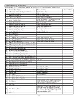
Figure 33. Outdoor Unit Main Board
31
DSP1
DOWN
MENU
3
4
5
6
7
8
9
10
11
12
14
15
16
18
19
20
21
22
23
24
26
27
28
29
30
OK
DSP2
32
33
34
1
2
UP
10
25
17
13
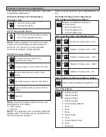
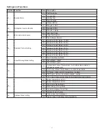
Digital Display
1.
Normal Display: When in standby, the digital
display will provide the address of the outdoor unit
and the quantity of the indoor units discovered.
2. Operating Display: When the outdoor unit is
in operation, the digital display will provide the
compressor(s) drive frequency.
#
Description
1
ON/OFF Signal Input Port for System Low Pressure
2
ON/OFF Signal Input Port for System High Pressure
3
Input port Voltage Leakage Detection
4
Temperature Detection Port of T10
5
Heatsink Temp. Detection Port of Inverter Module A
6
Heatsink Temp. Detection Port of Inverter Module B
7
Current Inspection Port of The Inverter Compressor A &
Compressor B
8
Temperature Detection Port of Outdoor Ambient &
Condenser Pipe (T4/T3A)
9
Detection Port of Condenser Pipe Temp. (T6B)
10 Comm. Port between Main Board & Compressor
Inverter Module
11 Comm. Port between Outdoor Units
12 Wiring Port for Communication
13 Power Input Port 24VAC
14 Power Output Port 5VDC
15 Control Port of EXV B
16 Control Port of EXV C
17 Input Port for Emergency Stop Switch
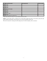
#
Description
18 Discharge Temp. Detection Port of Inv. Compressor A
19 Discharge Temp. Detection Port of Inv. Compressor B
20
Detection Port of Condenser Pipe Temp. (T3B)
21
Input Port for System High Pressure Detection
22 Input Port for System Low Pressure Detection
23
Detection Port of Condenser Pipe Temp. (T6A)
24 Communication Port between Main Board and Fan
Inverter Module
25 Communication Port between Main Board and low
ambient cooling kit
26 Communication Port between Main Board and LCD
Module
27 Reserved
28 Control Port of EXV A
29
Output Port for Crankcase Heater Of Compressor
30 Output Port for 4-Way Valve
31 Output Port for Solenoid Valve
32
Output Port for Base Pan Heater
33 Power Input Port
34 Voltage Detection Port
Содержание VPB Series
Страница 47: ...47...


