


Page 15
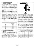
24VAC terminals and gas control switch are located on top
of the valve. All terminals on the gas valve are connected to
wires from the ignition control. 24V applied to the terminals
opens the valve.
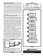
Inlet and outlet pressure taps are located on the valve. A
manifold adjustment screw is also located on the valve. An
LPG changeover kit is available.
FIGURE 13
Gas Valve
MANIFOLD
PRESSURE
OUTLET
PORT
INLET
PRESSURE
PORT
MANIFOLD
PRESSURE
ADJUSTMENT
SCREW
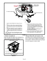
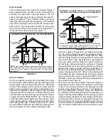
6. Flame Sensor (Figure 10)
A flame sensor is located on the left side of the burner sup
port. The sensor is mounted on the front burner box plate
and the tip protrudes into the flame envelope of the left-
most burner. The sensor can be removed for service with
out removing any part of the burners. During operation,
flame is sensed by current passed through the flame and
sensing electrode. The ignition control allows the gas valve
to remain open as long as flame signal is sensed.
NOTE - The ML195UH furnace contains electronic
components that are polarity sensitive. Make sure that
the furnace is wired correctly and is properly grounded.
A microamp DC meter is needed to check the flame signal
on the integrated control.
Flame (microamp) signal is an electrical current which
passes from the integrated control to the sensor during unit
operation. Current passes from the sensor through the
flame to ground to complete a safety circuit.
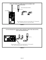
To Measure Flame Signal - Integrated Control:
Use a digital readout meter capable of reading DC micro
amps. See figure 14 for flame signal check.
1 - Set the meter to the DC amps scale.
2 - Turn off supply voltage to control.
3 - Disconnect integrated control flame sensor wire from
the flame sensor.
4 - Connect (-) lead to flame sensor.
5 - Connect (+) lead to the ignition control sensor wire.
6 - Turn supply voltage on and close thermostat contacts
to cycle system.
7 - When main burners are in operation for two minutes,
take reading.
7. Ignitor (Figure 10)
ML195UH units use a mini-nitride ignitor made from a pro
prietary ceramic material. Ignitor longevity is enhanced by
controlling the voltage to the ignitor. Units equipped with
control 103085 have a 120V ignitor. Units equipped with
control 100973 have a 95V ignitor. See figure 15 and table
8 for resistance and voltage checks.