Page 22
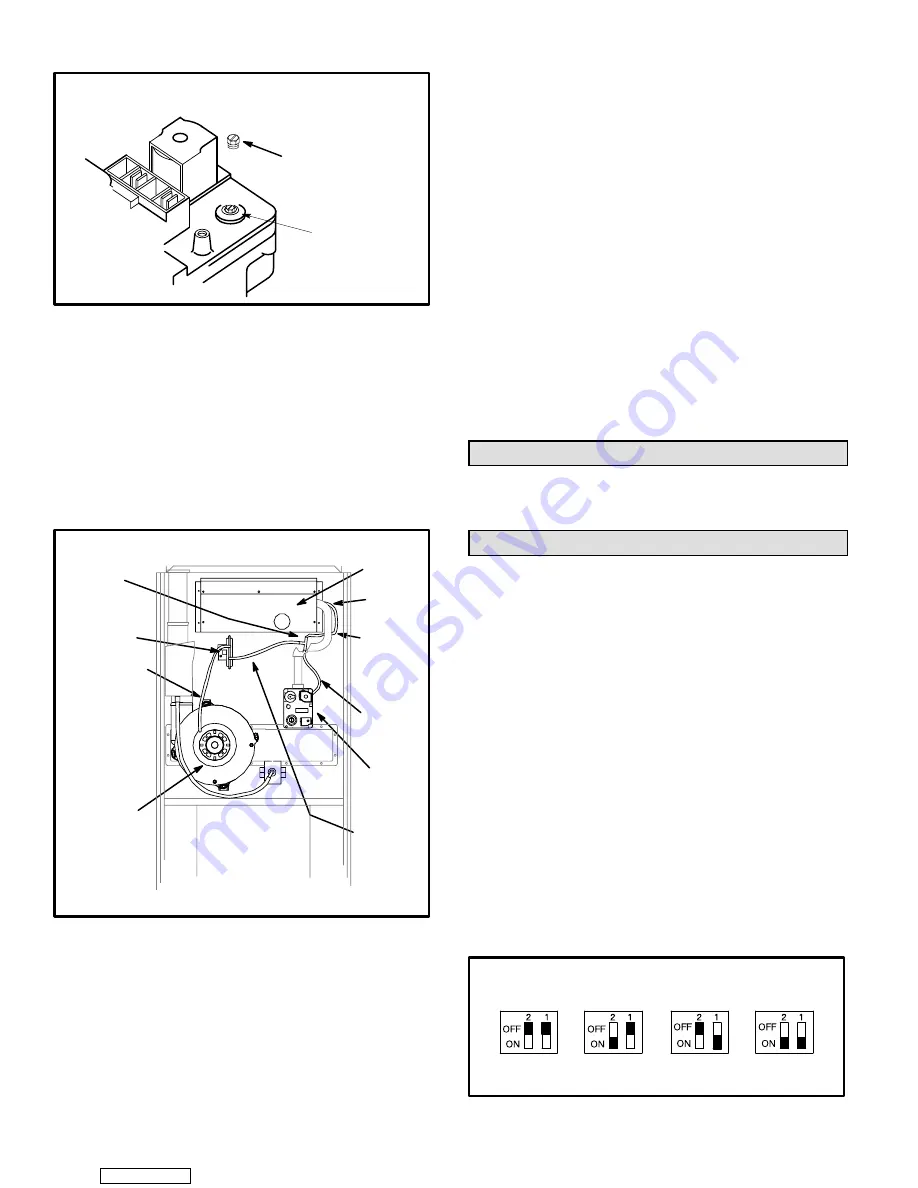
REGULATOR
COVER SCREW
FIGURE 35
WHITE RODGERS 36E GAS VALVE
REGULATOR ADJUSTMENT SCREW LOCATION
ADJUSTING
SCREW
Manifold Pressure Measurement & Adjustment
NOTE - Pressure test adaptor kit (10L34) is available from
Lennox to facilitate manifold pressure measurement.
1 - Connect test gauge to outlet tap on gas valve.
2 - Disconnect pressure sensing hose from gas valve and
plug hose by covering opening with tape or equivalent.
Leave barbed fitting on valve open to atmosphere.
See figure 36.
FIGURE 36
DIFFERENTIAL PRESSURE SWITCH CIRCUITRY
BURNER
BOX
GAS
VALVE
SENSING
HOSE
COMBUSTION
AIR PRESSURE
SENSING HOSE
COMBUSTION
AIR INDUCER
BURNER
BOX
SENSING
HOSE
GAS
VALVE
TEE
PRESSURE
SWITCH
SENSING
HOSE
HOSE
BARB
DIFFERENTIAL
PRESSURE
SWITCH
LEFT SIDE OF PRESSURE SWITCH = MORE NEGATIVE
RIGHT SIDE OF PRESSURE SWITCH = LESS NEGATIVE (Closer to Zero)
3 - Start unit and allow 5 minutes for unit to reach steady
state.
4 - Examine the burner flame. The flame should be stable
and should not lift from the burner. Natural gas should
burn blue. L.P./propane gas should burn mostly blue
with some orange streaks.
5 - After allowing unit to stabilize for 5 minutes, record
manifold pressure and compare to values given in
table 6.
NOTE - Shut unit off and remove manometer as soon as an
accurate reading has been obtained. Take care to replace
pressure tap plug.
NOTE - During this test procedure, the unit unit will be over-
firing:
D
Operate unit only long enough to obtain accurate reading to
prevent overheating heat exchanger.
D
Attempts to clock gas valve during this procedure will be
inaccurate. Measure gas flow rate only during nor-mal
unit operation.
6 - When test is complete remove obstruction from hose
and return hose to gas valve barbed fitting.
Gas Flow
To check for proper gas flow to the combustion chamber, deĆ
termine the Btu (kW) input from the unit rating plate. Divide
this input rating by the Btu (kW) per cubic foot (cubic meter)
of available gas. The result is the required number of cubic
feet (cubic meter) per hour. Determine the flow of gas
through the gas meter for two minutes and multiply by 30 to
get the hourly flow of gas.
High Altitude Information
Unit does not need gas pressure adjustment when operating
from 0 to 7500 feet (0 to 2248m). See table 6 for correct manĆ
ifold pressures for LP/propane and natural gases.
Other Unit Adjustments
Natural to LP/Propane Changeover
A natural gas to LP/propane gas changeover kit is required
to convert unit. Refer to installation instructions supplied
with kit for conversion procedure.
Heat Anticipation Settings
Thermostat anticipator setting (if adjustable) should be set
according to amps listed on wiring diagram on unit.
Flame Rollout Switch
Factory set: No adjustment necessary.
Limit Control
Factory set: No adjustment necessary.
Pressure Switch
Factory set: No adjustment is necessary.
Fan Control
The fan-on delay of 45 seconds is not adjustable. The fan-
off delay (time that the blower operates after the heating
demand has been satisfied) can be adjusted by moving the
jumper on the SureLight
t
integrated control. The unit is
shipped with a factory fan-off delay of 90 seconds. The fan-
off delay will affect comfort and is adjustable to satisfy indiĆ
vidual applications. See figure 37.
FIGURE 37
FANĆOFF TIME ADJUSTMENT
To adjust fan-off timing, flip dip switch to desired setting.
60sec.
90sec.
120sec.
180sec.
Downloaded from


