Lennox EL180DFE Series Скачать руководство пользователя страница 6

Page 6

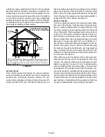
outside the space containing the furnace. This is especially
important when the furnace is mounted on a platform in a
confined space such as a closet or small equipment room.
Even a small leak around the base of the unit at the platform
or at the return air duct connection can cause a potentially
dangerous negative pressure condition. Air for combustion
and ventilation can be brought into the confined space either
from inside the building or from outside.

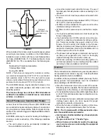
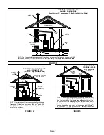
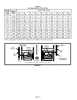
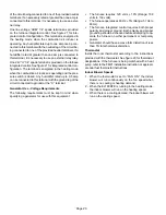
EQUIPMENT IN CONFINED

SPACE ALL AIR FROM INSIDE

CHIMNEY

OR GAS

VENT

FURNACE

WATER

HEATER

OPENINGS

(To Adjacent

Room)

NOTE - Each opening shall have a free area of at least one square
inch (645 mm

2

) per 1,000 Btu (.29 kW) per hour of the total input rat­

ing of all equipment in the enclosure, but not less than 100 square
inches (64516 mm

2

).

FIGURE 2

Air from Inside

If the confined space that houses the furnace adjoins a
space categorized as unconfined, air can be brought in by
providing two permanent openings between the two
spaces. Each opening must have a minimum free area of 1
square inch (645 mm

2

) per 1,000 Btu (.29 kW) per hour of

total input rating of all gas-fired equipment in the confined
space. Each opening must be at least 100 square inches
(64516 mm

2

). One opening shall be within 12 inches (305

mm) of the top of the enclosure and one opening within 12
inches (305 mm) of the bottom. See figure 2.
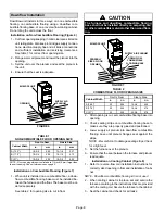
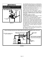
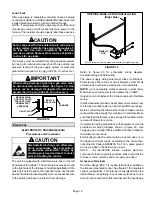
Air from Outside

If air from outside is brought in for combustion and ventila­
tion, the confined space must have two permanent open­
ings. One opening shall be within 12 inches (305 mm) of the
top of the enclosure and one opening within 12 inches (305
mm) of the bottom. These openings must communicate di­
rectly or by ducts with the outdoors or spaces (crawl or at­
tic) that freely communicate with the outdoors or indirectly
through vertical ducts. Each opening shall have a minimum
free area of 1 square inch (645 mm

2

) per 4,000 Btu (1.17

kW) per hour of total input rating of all equipment in the en­
closure. See


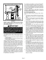
figures 3 and 4. When communicating with

the outdoors through horizontal ducts, each opening shall
have a minimum free area of 1 square inch (645 mm

2

) per

2,000 Btu (.56 kW) per total input rating of all equipment in
the enclosure. See


figure 5.

When ducts are used, they shall be of the same cross-sec­
tional area as the free area of the openings to which they
connect. The minimum dimension of rectangular air ducts
shall be no less than 3 inches (75 mm). In calculating free
area, the blocking effect of louvers, grilles, or screens must
be considered. If the design and free area of protective cov­
ering is not known for calculating the size opening required,
it may be assumed that wood louvers will have 20 to 25 per­
cent free area and metal louvers and grilles will have 60 to
75 percent free area. Louvers and grilles must be fixed in the
open position or interlocked with the equipment so that they
are opened automatically during equipment operation.

Содержание EL180DFE Series

Страница 1: ...stallation and service must be performed by a licensed professional installer or equivalent service agency or the gas supplier CAUTION As with any mechanical equipment personal injury can result from...

Страница 2: ...4 705 19 1 4 489 6 5 8 168 Right 7 1 8 181 Left 5 3 8 137 Right 2 3 16 56 Left 33 838 19 7 16 494 9 16 14 B Supply Air Supply Air 9 16 14 9 16 14 3 1 8 79 9 16 14 9 16 14 19 7 16 494 EL180DF Model No...

Страница 3: ...nces Adequate clearance must be made around the air open ings into the vestibule area In order to ensure proper unit operation combustion and ventilation air supply must be provided according to the c...

Страница 4: ...maintained during construction D Air filters must be replaced upon construction comple tion D The input rate and temperature rise must be set per the furnace rating plate D One hundred percent 100 out...

Страница 5: ...cient air causes incomplete combustion which can result in carbon monoxide CAUTION Insufficient combustion air can cause headaches nausea dizziness or asphyxiation It will also cause excess water in t...

Страница 6: ...re 2 Air from Outside If air from outside is brought in for combustion and ventila tion the confined space must have two permanent open ings One opening shall be within 12 inches 305 mm of the top of...

Страница 7: ...e square inch 645 mm2 per 4 000 Btu 1 17 kW per hour of the total input rating of all equip ment in the enclosure CHIMNEY OR GAS VENT WATER HEATER OUTLET AIR VENTILATION LOUVERS Each end of attic INLE...

Страница 8: ...the furnace and the floor The base must be or dered separately See table 2 for opening size to cut in floor CAUTION The furnace and downflow combustible flooring base shall not be installed directly o...

Страница 9: ...adversely affect the operation of the safety con trol devices which could result in personal injury or death Install the EL180DFE gas furnace as shipped in the downflow position only Do not install t...

Страница 10: ...alled in a space serviced by an exhaust fan power exhaust fan or other device which may create a negative pressure in the space take care when sizing the inlet air opening The in let air opening must...

Страница 11: ...y other gas fueled appliance i e water heater or carbon monoxide producing device i e wood fireplace is installed When return air is drawn from a room a negative pressure is created in the room If a g...

Страница 12: ...n a lined masonry chimney is used to vent this furnace A chimney with one or more sides exposed to the outside of the structure is considered to be an exterior chimney An exterior masonry chimney that...

Страница 13: ...servicing a solid fuel appliance If a fireplace chimney flue is used to vent this appliance the fireplace opening must be permanently sealed A type B or listed chimney lining system that passes throug...

Страница 14: ...constructed of listed double wall type B vent material or material having equivalent insulation qualities 14 All venting pipe passing through floors walls and ceil ings must be installed with the list...

Страница 15: ...22 339 5 22 65 30 130 39 219 49 330 10 29 59 40 121 51 206 64 315 15 35 53 48 112 61 195 76 301 20 0 0 97 0 202 0 349 0 540 2 10 75 14 149 18 250 20 377 5 21 71 29 143 38 242 47 367 10 28 64 38 133 50...

Страница 16: ...1 21 50 33 89 47 142 64 220 2 22 53 35 96 49 153 66 235 3 24 55 36 102 51 163 68 248 20 1 21 54 33 99 46 157 62 246 2 22 57 34 105 48 167 64 259 3 23 60 35 110 50 176 66 271 30 1 20 62 31 113 45 181...

Страница 17: ...properly step 3 return all doors widows exhaust fans fireplace damp ers and any other gas burning appliances to their pre vious mode of operation 7 If a venting problem is found during any of the prec...

Страница 18: ...0 32 56 985 27 89 873 24 72 791 22 39 728 20 61 677 19 17 635 17 98 600 17 00 2 50 8 2 067 52 502 4020 113 83 2760 78 15 2220 62 86 1900 53 80 1680 47 57 1520 43 04 1400 39 64 1300 36 81 1220 34 55 11...

Страница 19: ...the wires together Secure the excess wire to the existing harness to protect it from damage INTERIOR MAKE UP BOX INSTALLATION Right Side FIGURE 19 MAKE UP BOX Cut the two wire ties to extend power wi...

Страница 20: ...ground leg of the circuit connected to ground or the C terminal Generator Use Voltage Requirements The following requirements must be kept in mind when specifying a generator for use with this equipme...

Страница 21: ...Page 21 FIGURE 20 EL180DFE Schematic Wiring Diagram...

Страница 22: ...lame Sensed without gas valve energized 13 Low Line Voltage Notes Note 1 A Heartbeat is indicated by a Slow Flash 1 sec on 1 sec off repeating Note Error codes are indicated by a Rapid Flash the LED f...

Страница 23: ...er to the unit 4 This furnace is equipped with an ignition device which automatically lights the burners Do not try to light the burners by hand 5 Remove the access panel 6 Move switch on gas valve to...

Страница 24: ...f installed NOTE To obtain accurate reading shut off all other gas appliances connected to meter Supply Pressure Measurement A threaded plug on the inlet side of the gas valve provides access to the s...

Страница 25: ...o adjustment Flame Rollout Switches These manually reset switches are located on the burner box Pressure Switch The pressure switch is located in the heating compartment adjacent to the combustion air...

Страница 26: ...wer access panel 3 Disconnect existing speed tap at integrated control speed terminal NOTE Termination of any unused motor leads must be insulated 4 Place unused blower speed tap on integrated control...

Страница 27: ...ss and to make sure there is no blockage 2 Check unit for proper draft Electrical 1 Check all wiring for loose connections 2 Check for the correct voltage at the furnace furnace operating Correct volt...

Страница 28: ...by a licensed profes sional installer or equivalent service agency or gas supplier Cabinet Parts Heating access panel Blower access panel Top cap Control Panel Parts Transformer Integrated control Do...

Страница 29: ...sted Supply Line Pressure W C ________ 1 VENT EXHAUST PIPE Secure to Unit Elbows Secured to Pipe Vent Pipe Supported 2 Roof Flashing water tight 3 DUCT SYSTEM SUPPLY AIR DUCT Sealed Insulated if neces...

Страница 30: ...___ 5 COOLING MODE INDOOR BLOWER AMPS______ 3 TEMPERATURE DROP Return Duct Temperature _________ Supply Duct Temperature _ _______ 4 5 6 7 DRAIN LINE Leak Free THERMOSTAT Adjusted and Programmed Opera...

Отзывы: