background image

507281-06

Page 5 of 58

Issue 1724

Safety Information

Improper  installation,  adjustment,  alteration,  service 

or maintenance can cause property damage, personal 

injury  or  loss  of  life.  Installation  and  service  must  be 

performed  by  a  licensed  professional  installer  (or 

equivalent), service agency or the gas supplier.

 WARNING

As with any mechanical equipment, personal injury can 

result from contact with sharp sheet metal edges. Be 

careful when you handle this equipment. 

 CAUTION

DANGER OF EXPLOSION!

There  are  circumstances  in  which  odorant  used  with 

LP/Propane gas can lose its scent. In case of a leak, 

LP/Propane gas will settle close to the floor and may be 

difficult to smell. An LP/Propane leak detector should be 

installed in all LP applications.

 DANGER

Use only the type of gas approved for use with this furnace. 

Refer to unit nameplate.

A95UH2E/95G2UHE units are CSA International certified 

to ANSI Z21.47 and CSA 2.3 standards.

Building Codes

In the USA, installation of gas furnaces must conform with 

local building codes. In the absence of local codes, units 

must  be  installed  according  to  the  current  National  Fuel 

Gas Code (ANSI Z223.1/NFPA 54). The National Fuel Gas 

Code is available from the 

American National Standards 

Institute, Inc., 11 West 42nd Street, New York, NY 10036

.

In Canada, installation must conform with current National 

Standard of Canada CSA-B149 Natural Gas and Propane 

Installation  Codes,  local  plumbing  or  waste  water  codes 

and other applicable local codes.

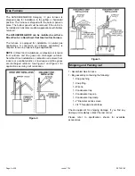
In order to ensure proper unit operation in non-direct vent 

applications,  combustion  and  ventilation  air  supply  must 

be  provided  according  to  the  current  National  Fuel  Gas 

Code or CSA-B149 standard.
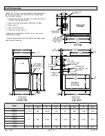
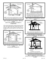
Installed Locations

This furnace is CSA International certified for installation 

clearances  to  combustible  material  as  listed  on  the  unit 

nameplate  and  in  the  table  in  Figure  13  and  Figure  18. 

Accessibility and service clearances must take precedence 

over fire protection clearances.

NOTE

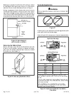
For installation on combustible floors, the furnace 

shall  not  be  installed  directly  on  carpeting,  tile,  or  other 

combustible material other than wood flooring.

For installation in a residential garage, the furnace must be 

installed so that the burner(s) and the ignition source are 

located no less than 18 inches (457 mm) above the floor. 

The furnace must be located or protected to avoid physical 

damage by vehicles. When a furnace is installed in a public 

garage,  hangar,  or  other  building  that  has  a  hazardous 

atmosphere,  the  furnace  must  be  installed  according  to 

recommended  good  practice  requirements  and  current 

National Fuel Gas Code or CSA B149 standards.

NOTE

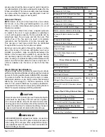
Furnace must be adjusted to obtain a temperature 

rise  within  the  range  specified  on  the  unit  nameplate. 

Failure  to  do  so  may  cause  erratic  limit  operation  and 

premature heat exchanger failure.

This  furnace  must  be  installed  so  that  its  electrical 

components are protected from water.

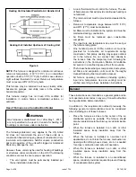
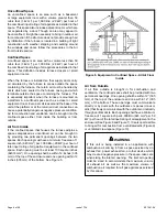
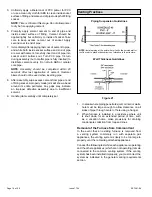
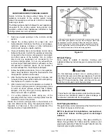
Installed in Combination with a Cooling Coil

When  this  furnace  is  used  with  cooling  units  (Figure  4), 

it  shall  be  installed  in  parallel  with,  or  on  the  upstream 

side of, cooling units to avoid condensation in the heating 

compartment. With a parallel flow arrangement, a damper 

(or other means to control the flow of air) must adequately 

prevent chilled air from entering the furnace. If the damper 

is  manually  operated,  it  must  be  equipped  to  prevent 

operation of either the heating or the cooling unit, unless it 

is in the full HEAT or COOL setting.

When installed, this furnace must be electrically grounded 

according to local codes. In addition, in the United States, 

installation  must  conform  with  the  current  National 

Electric  Code, ANSI/NFPA  No.  70.  The  National  Electric 

Code (ANSI/NFPA No. 70) is available from the following 

address:

National Fire Protection Association

1 Battery March Park

Quincy, MA 02269

In Canada, all electrical wiring and grounding for the unit 

must  be  installed  according  to  the  current  regulations  of 

the Canadian Electrical Code Part I (CSA Standard C22.1) 

and/or local codes.

Содержание 95G2UHE

Страница 1: ...hanical equipment personal injury can result from contact with sharp sheet metal edges Be careful when you handle this equipment CAUTION Improper installation adjustment alteration service or maintena...

Страница 2: ...9 3 4 19 1 Bottom Return Air Opening GAS PIPING INLET Either Side Side Return Air Opening Either Side 1Bottom Return Air Opening EXHAUST AIR OUTLET ELECTRICAL INLET Either Side SUPPLY AIR OPENING W E...

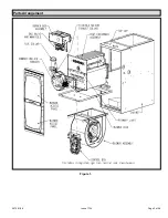
Страница 3: ...507281 06 Page 3 of 58 Issue 1724 Figure 1 Parts Arrangement...

Страница 4: ...pane LP gas applications NOTE In Direct Vent installations combustion air is taken from outdoors and flue gases are discharged outdoors Non Direct Vent installations combustion air is taken from indoo...

Страница 5: ...nces must take precedence over fire protection clearances NOTE For installation on combustible floors the furnace shall not be installed directly on carpeting tile or other combustible material other...

Страница 6: ...lling one of these furnaces Place the furnace as close to the center of the air distribution system as possible The furnace should also be located close to the chimney or vent termination point When t...

Страница 7: ...es to ensure efficient and safe operation You must consider combustion air needs and requirements for exhaust vents and gas piping A portion of this information has been reprinted with permission from...

Страница 8: ...he building or from outside Air from Inside If the confined space that houses the furnace adjoins a space categorized as unconfined air can be brought in by providing two permanent openings between th...

Страница 9: ...penings shall each have a free area of at least one square inch per 4 000 Btu 645mm2per 1 17kW per hour of the total input rating of all equipment in the enclosure Ventilation Louvers Inlet Air Minimu...

Страница 10: ...ck to front to aid in the draining of the heat exchanger Unit must be level side to side in all applications When ducts are used they shall be of the same cross sectional area as the free area of the...

Страница 11: ...or either side of the furnace installed in an upflow application If the furnace is installed on a platform with bottom return make an airtight seal between the bottom of the furnace and the platform t...

Страница 12: ...ottom panel has been removed reinstall the bottom cap See Figure 16 Figure 16 Removing the Bottom Panel Horizontal Applications Do not install the furnace on its front or its back See Figure 13 WARNIN...

Страница 13: ...a crawl space a proper support platform may be created using cement blocks 4 Route auxiliary drain line so that water draining from this outlet will be easily noticed by the homeowner 5 If necessary r...

Страница 14: ...lowing and contain no lumps undissolved particles or any foreign matter that adversely affects the joint strength or chemical resistance of the cement The cement shall show no gelation stratification...

Страница 15: ...2855 DANGER OF EXPLOSION Fumes from PVC glue may ignite during system check Allow fumes to dissipate for at least 5 minutes before placing unit into operation DANGER 1 Measure and cut vent pipe to des...

Страница 16: ...t will show a bead around its entire perimeter Any gaps may indicate an improper defective assembly due to insufficient solvent 9 Handle joints carefully until completely set Venting Practices Figure...

Страница 17: ...any other gas burning appliances to their previous mode of operation 7 If a venting problem is found during any of the preceding tests the common venting system must be modified to correct the problem...

Страница 18: ...stems which include multiple pipe sizes NOTE All horizontal runs of exhaust pipe must slope back toward unit A minimum of 1 4 6 mm drop for each 12 305 mm of horizontal run is mandatory for drainage N...

Страница 19: ...78 74 9 36 21 70 70 48 13 93 92 73 73 69 10 31 16 65 65 43 8 89 87 68 68 64 Standard Termination at Elevation 4 501 10 000 ft Number of 90 Elbows Used 2 Pipe 2 1 2 Pipe 3 Pipe Model Model Model 45 70...

Страница 20: ...65 9 28 13 60 60 44 9 76 76 69 69 60 10 23 8 55 55 39 n a 71 71 64 64 55 Concentric Termination at Elevation 4 501 10 000 ft Number of 90 Elbows Used 2 Pipe 2 1 2 Pipe 3 Pipe Model Model Model 45 70 9...

Страница 21: ...73 72 53 53 49 10 16 6 50 50 28 68 67 48 48 44 Standard Termination at Elevation 4 501 10 000 ft Number of 90 Elbows Used 2 Pipe 2 1 2 Pipe 3 Pipe Model Model Model 45 70 90 110 135 45 70 90 110 135...

Страница 22: ...he shortest length of 2 PVC pipe possible NOTE Exhaust pipe and intake pipe must be the same diameter Figure 25 Typical Exhaust Pipe Connections in Horizontal Direct or Non Direct Vent Applications Ri...

Страница 23: ...on direct vent applications when intake air will be drawn into the furnace from the surrounding space the indoor air quality must be considered and guidelines listed in the Combustion Dilution Ventila...

Страница 24: ...ill not be obstructed by loose insulation or other items that may clog the debris screen 4 If intake air is drawn from a ventilated attic Figure 30 or ventilated crawlspace Figure 31 the exhaust vent...

Страница 25: ...als prolonged exposure to exhaust condensate can destroy protective coatings It is recommended that the exhaust outlet not be located within 6 feet 1 8 m of a condensing unit because the condensate ca...

Страница 26: ...nt installations combustion air is taken from outdoors and flue gases are discharged to outdoors NOTE Flue gas may be slightly acidic and may adversely affect some building materials If any vent termi...

Страница 27: ...ulation of exhaust back into intake pipe 5 On field supplied terminations for sidewall exit exhaust piping may extend a maximum of 12 inches 305 mm for 2 PVC and 20 inches 508 mm for 3 76 mm PVC beyon...

Страница 28: ...VENT INTAKE AIR Inches MM Side View 12 305MM Min above grade or average snow accumulation optional intake elbow Figure 41 Direct Vent Application Using Existing Chimney 3 8 76MM 203MM STRAIGHT CUT OR...

Страница 29: ...within a height 15 feet 4 5m above the meter regulator assembly 3 feet 9m 6 inches 152mm for appliances 10 000 pliances 10 000 Btuh 3kw and 50 000 pliances 50 000 Btuh 15kw 6 inches 152mm for applianc...

Страница 30: ...3 76MM Vent Pipe A Clearance above grade or average snow accumulation B Horizontal separation between intake and exhaust C Minimum from end of exhaust to inlet of intake D Exhaust pipe length E Wall s...

Страница 31: ...inlet Clearance above paved sidewalk or paved driveway located on public property Clearance under veranda porch deck or balcony 12 Equal to or greater than soffit depth 3 feet 9m 12 3 feet 9m within a...

Страница 32: ...igure 47 When exhaust piping must be run up an outside wall any reduction in exhaust pipe size must be done after the final elbow Figure 45 Non Direct Vent Roof Termination Kit 15F75 or 44J41 Figure 4...

Страница 33: ...ermination Drain Trap assembled Figure 49 Kit 51W18 USA 15Z70 Canada Parts Identification and Assembly Exhaust from Furnace To Termination Exhaust from Furnace To Termination Kit 51W18 is shown Figure...

Страница 34: ...ate line must maintain a 1 4 downward slope from the furnace to the drain Do not use copper tubing or existing copper condensate lines for drain line CAUTION 5 Figure 54 and Figure 55 show the furnace...

Страница 35: ...sition with remote trap Piping from furnace must slope down a minimum of 1 4 per ft toward trap Figure 54 Unit With Evaporator Coil Figure 55 Condensate Trap Locations Unit shown in horizontal right h...

Страница 36: ...must be vented to relieve pressure in order for the furnace pressure switch to operate properly IMPORTANT Figure 56 Condensate Trap with Optional Overflow Switch Figure 57 Evaporator Coil using a Com...

Страница 37: ...nished Drain Assembly for 3 4 inch Drain Pipe Condensate Drain Connection In Unit Condensate Drain Connection In Unit Vent To Drain Condensate Drain Connection In Unit Optional Condensate Drain Connec...

Страница 38: ...using suitable hangers or straps Install a drip leg in vertical pipe runs to serve as a trap for sediment or condensate 5 A 1 8 N P T plugged tap or pressure post is located on the gas valve to facil...

Страница 39: ...ications a 4 BIP nipple must be installed to allow clearance for the low inlet pressure switch AUTOMATIC GAS VALVE with manual shut off valve Figure 62 Horizontal Applications Possible Gas Piping Conf...

Страница 40: ...16 42 530 15 01 490 13 87 460 13 03 430 12 18 400 11 33 1 1 2 38 1 1 610 40 894 2100 59 46 460 41 34 1180 33 41 990 28 03 900 25 48 810 22 94 750 21 24 690 19 54 650 18 41 620 17 56 2 50 8 2 067 52 50...

Страница 41: ...fuse or circuit breaker select circuit protection and wire size according to unit nameplate NOTE Unit nameplate states maximum current draw Maximum over current protection allowed is shown in Table 9...

Страница 42: ...and proper grounding should be checked before attempting to operate the furnace on either permanent or temporary power Generator should have a wave form distortion of less than 5 THD total harmonic di...

Страница 43: ...TR CHASSIS GROUND GRD Y1 THERMOSTAT 1ST STAGE COOL SIGNAL Y2 THERMOSTAT 2ND STAGE COOL SIGNAL O THERMOSTAT SIGNAL TO HEAT PUMP REVERSING VALVE L NOT USED DH NOT USED 3 16 QUICK CONNECT TERMINALS FLAM...

Страница 44: ...the ON position it will provide a 12 minute delay before second stage heat is initiated This switch is only activated when the thermostat selector jumper is positioned for single stage thermostat use...

Страница 45: ...507281 06 Page 45 of 58 Issue 1724 Table 13A Field Wiring Applications With Conventional Thermostat...

Страница 46: ...507281 06 Page 46 of 58 Issue 1724 Table 13B Field Wiring Applications With Conventional Thermostat Continued...

Страница 47: ...Field Wiring Applications With Conventional Thermostat Continued Connect W1 to W1 ONLY if using defrost tempering kit 67M41 NOTE DO NOT make a wire connection between the room thermostat L terminal a...

Страница 48: ...Field Wiring Applications With Conventional Thermostat Continued Connect W1 to W1 ONLY if using defrost tempering kit 67M41 NOTE DO NOT make a wire connection between the room thermostat L terminal a...

Страница 49: ...507281 06 Page 49 of 58 Issue 1724 Figure 66...

Страница 50: ...ically light The ignitor does not get hot when there is no call for heat on these units Gas Valve Operation 1 STOP Read the safety information at the beginning of this section 2 Set the thermostat to...

Страница 51: ...f flame is not detected after first ignition trial the ignition control will repeat steps 3 and 4 four more times before locking out the gas valve The ignition control will then automatically repeat s...

Страница 52: ...ximum carbon monoxide reading should not exceed 100 ppm High Altitude Information NOTE In Canada certification for installations at elevations over 4500 feet 1371 m is the jurisdiction of local author...

Страница 53: ...tts cfm Watts cfm Watts 0 00 1380 315 1305 250 1190 200 965 105 920 100 0 10 1360 325 1270 255 1180 205 915 115 865 100 0 20 1310 335 1250 265 1130 215 880 120 815 110 0 30 1275 340 1205 275 1100 225...

Страница 54: ...Sides or Return Air from Bottom and One Side Single Side Return Air Air volumes in bold require field fabricated transition to accommodate 20 x 25 x 1 in air filter in order to maintain proper air ve...

Страница 55: ...condensate water 3 Remove the clean out cap from the condensate trap and empty water Inspect the trap then reinstall the clean out cap Cleaning Heat Exchanger If cleaning the heat exchanger becomes ne...

Страница 56: ...lexible no hub connector Reconnect the 2 pin plug to the wire harness 38 Reconnect drain tubes between flue collar and cold end header box 39 Secure burner assembly to vestibule panel using four exist...

Страница 57: ...ons Problems detected during the inspection may make it necessary to temporarily shut down the furnace until the items can be repaired or replaced Instruct the homeowners to pay attention to their fur...

Страница 58: ...imum height of eight 8 feet above grade directly in line with the exhaust vent terminal for the horizontally vented gas fueled heating appliance or equipment The sign shall read in print size no less...

Отзывы: