41
SINGLE PASS HALF-BLIND DOVETAILS
Chapter 11
D4R Pro User Guide
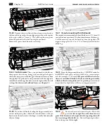
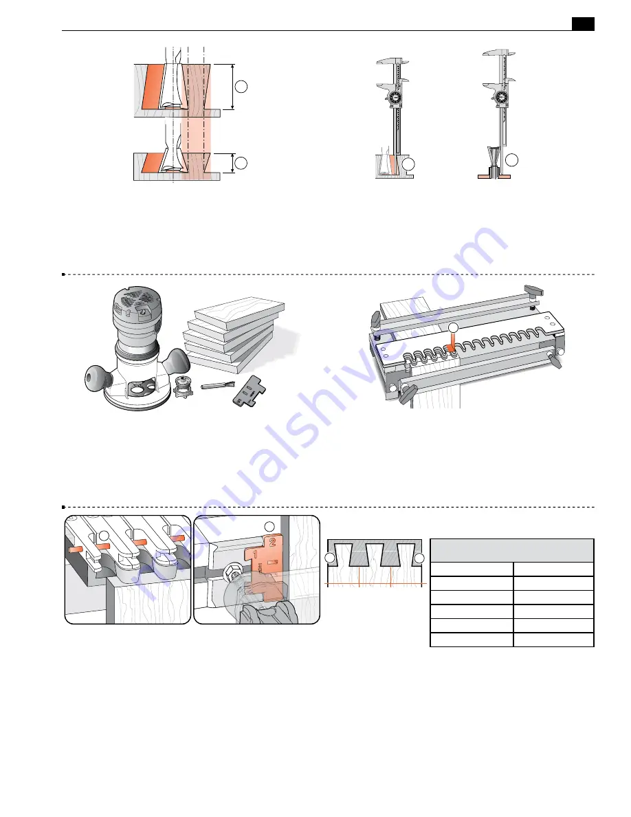
11-3 Bit Angle and Depth of Cut
Half-blind pins and tails
are routed with the
same
dovetail bit, the
same
guidebush, and
the
same
depth of cut. A different depth of cut requires a differ-
ent angled bit. Leigh offers five different angled dovetail bits for
a range of cut depths. A lesser angle, say 8˚, for a deeper cut
➀
; a
greater angle, say 18˚, for a shallower cut
➁
.
1
2
18˚
8˚
11-4
Cumulative plus/minus tolerances in routers, bits and
guidebushes, make it impossible to state exact bit depth for first-
time precision fit. All dovetail jigs require trial and error tests to
attain a fine fitting joint. The good news; we give a starting depth
for each bit. Test and measure the successful ‘Best fit’ depth of
cut
➀
or bit projection
➁
and record for future first-time fits.
1
2
Depth
of Cut
Bit
Projection
11-5 Routing a Test Joint
You need a router, the
e7-Bush
set at No.10 (see chapter 3 for
e-Bush
instructions) and the 80-8
1
⁄
2
"[12,7mm] 8˚ dovetail bit. Note: The No.80-8 bit routs at a
shallower ~
1
⁄
2
"[13mm] depth on single pass dovetails than on
regular variably spaced joints. For this test, start with the No.80-8
bit projecting
15
⁄
16
"[24mm] from the router base.
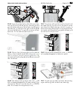
11-6
This is a typical fixed template comb type jig. The comb
depth
➀
is usually dimensioned to suit the most popular drawer
side thickness of
1
⁄
2
"[12,7mm].
1
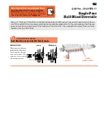
11-7 Stop Rod and Dovetail Spacer
The stop rod is inserted
in the fingers
➀
to convert them from deep tail sockets to a shallow
fixed comb. The flexible stop rod is fed through the holes in the
fingers from the “far” end of the jig. The
Dovetail Spacer
(note
the dovetail shaped notch) snaps into the channel against the left-
hand front side stop
➁
to correctly offset the drawer sides from
the drawer fronts. After setup, the Spacer stays in place for the
complete procedure.
1
2
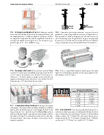
11-8 Board Widths
To achieve equally sized half pins
➀
at
each side on a fixed space joint, use the board width from the chart
above. Alternatively, you can add up to
1
⁄
4
"[6mm] to the listed board
width, or reduce it by
1
⁄
8
"[3mm]. This chart covers boards up to a
maximum width of 13
1
⁄
16
"[331mm]. Example: the 12"[305mm]
can be up to 12
1
⁄
4
"[311mm] or as small as 11
7
⁄
8
"[302mm].
1
1
Single Pass Board Width Chart
Add up to ¼" [6mm] or subtract up to 1/8" [3mm]
2
3
⁄
16
[55]
8
11
⁄
16
[221]
3
1
⁄
4
[83]
9
3
⁄
4
[248]
4
3
⁄
8
[110]
10
7
⁄
8
[276]
5
7
⁄
16
[138]
12 [305]
6
1
⁄
2
[166]
13
1
⁄
16
[331]
7
5
⁄
8
[193]
–
Содержание D4R Pro
Страница 14: ...JIG ASSEMBLY MOUNTING AND USING THE CLAMPS 6 Chapter 1 D4R Pro User Guide ...
Страница 24: ...WOOD PREPARATION 16 Chapter 6 D4R Pro User Guide ...
Страница 86: ...BIT SELECTION 78 Appendix II D4R Pro User Guide ...
Страница 90: ...JIG PARTS 82 Appendix III D4R Pro User Guide ...
Страница 92: ...PRINTED IN CANADA Joining Tradition with Today Printed in Canada ...


