ProVision 3 Installation Manual
8100-35521-00
Rev. A1
Leidos Security Detection & Automation, Inc.
–
Proprietary
Page 55 of 119
© 2020 Leidos. All rights reserved
6.
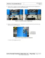
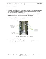
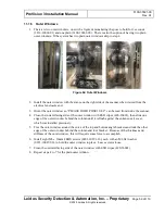
Connect the BNC connectors of the five color-coded cables to the ISU, matching each to its color-
coded or color-labeled connector. From the D-sub connector, shown at the right side of the following
figure right, the sequence is red (R), green (G), orange (OR), blue (BL), yellow (Y).
7.
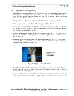
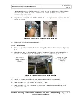
Secure the cables to the swing arm using a zip tie at the point shown in the previous figure and two
zip tie points located on the inner portion of the swing arm.
8.
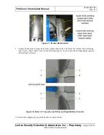
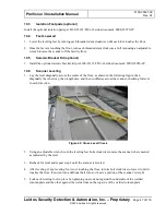
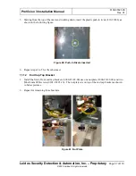
Cut a small piece of corrugated tube approximately 15cm (6 inches) and slip over the mast antenna
cables so that the cables are not sitting on the swing arm frame shown in figure below. Secure with
two zip ties at both ends of the tube.
Figure 56: Corrugated Tube
Figure 57: Connectors on ISU and Cables from Mast Connected to ISU

