3
COVERAGE PATTERN
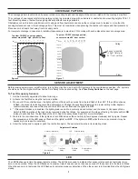
The coverage pattern is determined by sensor model, mounting height and the angle of the sensor, relative to the coverage area floor.
The coverage shown represents full-step walking motion in a carpeted area, with no barriers or obstacles at a mounting height of 8 to 10
feet. Mounting above or below this range significantly affects coverage patterns.
Obstacles such as furniture or partitions, wall, ceiling and floor treatments can cause the coverage area to be less or more than the
sensing distances shown in the coverage pattern. This must be considered when planning the number of sensors and their placement.
Place sensors at least 4 feet away from air supply ducts.
For complete coverage in open areas, install multiple sensors to provide a 20% overlap with each adjacent sensor’s coverage area.
P
P
P
P
P
P
P
P
P
P
IHHWPHWHUV
P
P
P
P
P
P
P
P
P
P
P
IURP
YHUWLFDO
IHHWPHWHUV
6HQVRUPRXQWHG
LQOLJKWIL[WXUHDW
IURPYHUWLFDO
)ORRU
&HLOLQJ
:
DOO
Top view, FS-555C coverage pattern,
sensor mounted 8’ high, parallel to floor
Top view, FS-555 coverage pattern,
sensor mounted 20
o
from vertical
Figure 6.
Figure 7.
SENSOR ADJUSTMENT
Before making adjustments, install furniture, turn lighting circuits on, and set HVAC systems to the overridden/on position. VAV systems
should be set to their highest airflow. Set the Time Delay to the desired setting. See
Time Delay Switches
on the next page.
To Test Occupancy Sensors
1. Set the Sensitivity adjustment to about mid-range.
2. Activate the Test Mode using the test mode button.
3. Move out of the controlled area - the lights will turn off in about 5 seconds from the last flash of the LED.* If the LED continues
to flash, the sensor is detecting some kind of movement. Change the sensitivity adjustment to a lower setting (a few degrees
counterclockwise) and repeat this step until the LED does not flash and the lights turn
OFF
.
4. * If Reverse-Occupancy is enabled (the lighting load is wired to a normally closed contact and the sensor’s Occupancy Mode
Switch is
ON
), operation of the load is also reversed during Test Mode. For example, at this stage of testing, the lights will turn
ON
in about 5 seconds from the last flash of the LED. See Occupancy Mode Switch for more information.
5. Walk into the controlled area. If the lights don’t turn
ON
, increase the sensitivity (a few degrees clockwise) and try again. Repeat
this procedure until the LED does not flash and the lights turn
OFF
. If the lights turn
OFF
while the room is occupied, it may be
necessary to increase the sensitivity.
6. Allow the test period to expire or push the test button again. The sensor will now be in its operating mode.
7LPH'HOD\
6HWWLQJ
6HQVLWLYLW\6HWWLQJ
2FFXSDQF\0RGH
6HWWLQJ
7HVW0RGH
%XWWRQ
0ROHV
/('
8OWUDVRQLF7UDQVGXFHU
21
21
2
Adjustment Features
Figure 8.
LED
The LED flashes every time the sensor detects motion. The LED is also used to indicate other sensor status such as test mode, lamp
burn-in, and override. When the LED flashes at a constant rate of one second on then one second off, the sensor is in the Burn-In Mode.
When the sensor is in test mode the LED flashes to indicate occupancy detections. When the sensor is in Override Mode the LED glows
steady.


