


21
KEOR T
Installa
tion M
anual
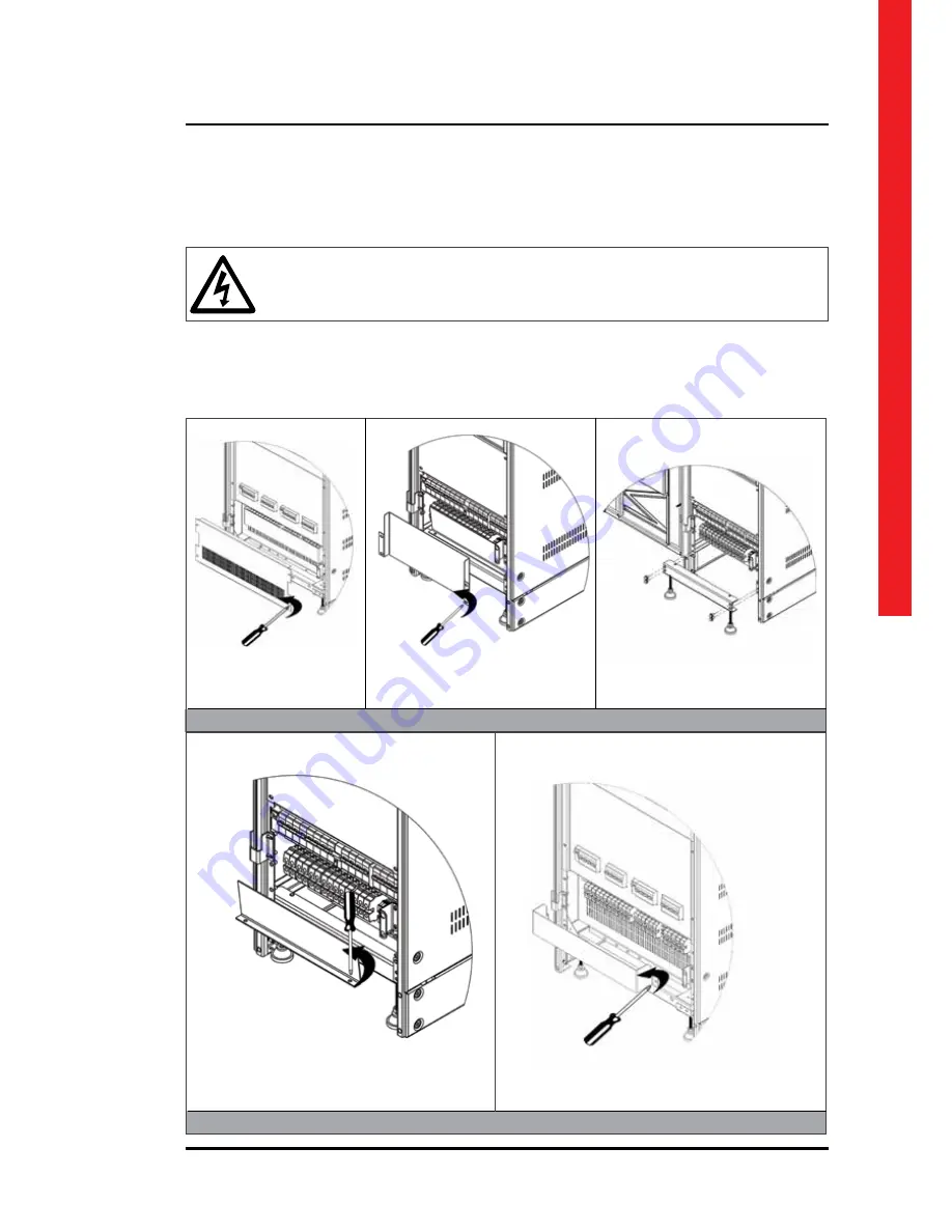
Make sure that all circuit breakers are “OFF” before starting with the installation.
Figure.5.3.1-4
Figure.5.3.1-1
Figure.5.3.1-2
Figure.5.3.1-3
Figure.5.3.1-5
The power screw terminals are located on the lower front side of the UPS.
Firstly, open the UPS door, screw out of the metal cover, afterwards open plastic cover of terminals.
After the covers are removed, the cables shall be passed through the hole under the terminals.
After all connections done, replace the covers in order.
5.3.1.
Power Connections of Single Systems
10-30kVA KEOR T
40-60kVA KEOR T
Содержание KEOR T
Страница 1: ...KEOR T Installation Manual LE07544AA ...
Страница 2: ...2 KEOR T ENGLISH 6 EN ...
Страница 5: ...5 KEOR T Installation Manual Battery Fast Fuses Installation Operating Manuals ...
Страница 32: ...32 Figure 5 3 1 4 1 Keor T 10 30kVA 1x60pcs 7 9Ah BATTERY WIRING DIAGRAM ...
Страница 33: ...33 KEOR T Installation Manual Figure 5 3 1 4 2 Keor T 10 30kVA 2x60pcs 7 9Ah BATTERY WIRING DIAGRAM ...
Страница 34: ...34 Figure 5 3 1 4 3 Keor T 40 60kVA 2x60pcs 7 9Ah BATTERY WIRING DIAGRAM ...
Страница 35: ...35 KEOR T Installation Manual Figure 5 3 1 4 4 Keor T 40 60kVA 3x60pcs 7 9Ah BATTERY WIRING DIAGRAM ...
Страница 50: ...50 SEPARATED RECTIFIER AND BYPASS INPUTS ...
Страница 51: ...51 KEOR T Installation Manual COMMON RECTIFIER AND BYPASS INPUTS ...


