background image

51

EN

Follow this procedure to change the buzzer setting:

- press the 

. The buzzer setting is displayed;

- press 

 to select ON or OFF;

- confirm the choice by pressing 

.

The quick battery test can be performed to check the operation of the batteries. The test must be 

performed only after the batteries are fully charged, the mains is available and the UPS is powering 

the loads. Follow this procedure to perform the battery test: 
- press 

;

- press 

 to display the battery test setting;

- press 

 to select ON. The UPS transfers to stored energy mode for 10 seconds. During the test, 

the loads are always powered with no voltage dip;

- if at the end of the test the UPS transfers back to normal mode without any alarm code, the bat-

teries are working properly. 

To change all the other settings, the UPS must be in standby mode. In this condition the loads are 

not powered, therefore all the needed settings must be performed before turning on the UPS.

Follow this procedure to change the UPS settings:

-  press simultaneously 

 and 

 for approximately three seconds, until the buzzer sounds 

twice. The LCD displays the first setting indicated in the next table (“buzzer”);

-  all the different settings can be scrolled pressing 

;

-  except for the buzzer and the battery test, all the other settings may be changed by pressing 

;

-  after changing settings, scroll to the “End” screen and then press 

 to save all changes;

-  the UPS restarts automatically. However, it is also suggested to remove the mains for at least 30 

seconds.

DAKER DK Plus

1 kVA - 3 kVA

Содержание DAKER DK Plus Series

Страница 1: ...DAKER DK Plus 1 kVA 3 kVA Manuel d installation Installation manual ...

Страница 2: ...41 3 4 Rear panel 43 3 5 Installation procedure 44 4 Operation 45 4 1 Control Panel 45 4 1 1 LCD Panel 45 4 1 2 Display description 46 4 2 Operating modes 47 4 3 Start up procedure 48 4 3 1 Normal mode 48 4 3 2 Cold start 48 4 4 Shutdown 49 4 5 UPS Measurements 49 4 6 UPS settings 50 4 7 Settings shortcuts 55 4 8 Emergency Power Off EPO 55 4 9 Communication devices 56 5 Troubleshooting 57 6 Wareho...

Страница 3: ... only in residential commercial industrial environments The following diagram illustrates the architecture of the UPS system The major modules consist of An AC to DC power converter rectifier with PFC control circuit A DC to AC high frequency inverter A battery charger A battery bank A DC to DC push pull converter control circuit A static bypass loop Input and output EMI filters ...

Страница 4: ...arising from failure to observe the installation instructions and use of the equipment which differs from the specifications in the installation manual use by personnel who have not read and thoroughly understood the content of the installation manual use that does not comply with the specific standards used in the country where the equipment is installed modifications made to the equipment softwa...

Страница 5: ... internal parts To isolate the UPS unplug it from the mains power socket Do not attempt to open or disassemble the UPS there are no user replaceable parts Opening the case will void the warranty and introduces the risk of electric shock even when the mains plug is disconnected The mains socket outlet that supplies the UPS shall be installed near the UPS and shall be easily accessible Do not plug n...

Страница 6: ...f temperature between 0 C 32 F and 40 C 104 F and non condensing humidity between 20 and 80 Do not install the UPS in locations with sparks smoke and hazardous gas or where there is water and excessive humidity Dusty corrosive and salty environments can damage the UPS Do not plug the UPS input into its own output Do not attach a power strip or surge suppressor to the UPS Do not cover the cooling v...

Страница 7: ...38 3 Installation 3 1 Package content Check for the following package content ...

Страница 8: ...EN 39 3 2 Tower configuration setup 3 2 1 UPS DAKER DK Plus 1 kVA 3 kVA ...

Страница 9: ...40 3 2 2 UPS battery cabinet optional 3 Installation S1 ...

Страница 10: ...configuration setup INDICATION For the rack configuration setup it is also possible to use the rack support bracket kit 3 109 52 In this case follow the instruction sheet contained in the kit DAKER DK Plus 1 kVA 3 kVA ...

Страница 11: ...42 3 Installation ...

Страница 12: ...y Power Off EPO 2 USB port 3 RS 232 port 4 Cooling fans 5 External battery connector 6 SNMP slot 7 AC input inlet 8 Input circuit breaker 9 Output circuit breakers 10 IEC type F outlets 11 IEC type J outlet DAKER DK Plus 1 kVA 3 kVA ...

Страница 13: ...e in the following figure 2 Connect the IEC input and output cables provided to the appropriate inlet and outlets 3 Connect the loads to the IEC output cables ensuring that the switches of the various loads are in the off position 4 Plug the UPS input cable into a main socket with a suitable voltage and current 5 Connect the EPO contact in the UPS normally closed 3 Installation ...
Страница 14: ...utlets 1 and 2 are activated e The green LED blinks if the UPS is in bypass mode The steady green LED indicates that the UPS is in ECO mode f The steady red LED indicates that there is an alarm g UPS power ON Silence alarm h UPS power OFF i Special functions access menu j Go to the next screen k Go to the previous screen or change the setting of the UPS l Confirm a changed setting 4 Operation DAKE...

Страница 15: ...s Fault Utility Input Fault Site wiring Fault Buzzer Silent Overload UPS Service mode reserved for LEGRAND Technical Support Service Alarm UPS operation diagram 3 Digit Measurement Display Measured item Battery fault Battery low Battery test 4 Operation ...

Страница 16: ...graph 4 7 a generic alarm or a prolonged overload in normal mode LEDs steady DISPLAY Beep every two seconds ECO MODE The loads are supplied directly from the mains through the automatic bypass circuit inside the UPS The output voltage and frequency are the same as the mains LEDs steady DISPLAY No sound CVCF 50 60 The UPS maintains constant the output voltage and the output fre quency to 50 Hz or 6...

Страница 17: ...he green LEDs light up The display looks like the following figure 5 The start up procedure is completed Make sure that the batteries are fully charged or that the UPS has been plugged to the wall receptacle at least for 4 hours before connecting the loads 4 3 2 Cold start 1 Make sure the internal batteries or the external battery cabinets are connected to the UPS 2 Press and hold it until the buz...

Страница 18: ...60 Hz then the output frequency after the cold start will be 60 Hz 4 4 Shutdown 1 Press and hold until the buzzer sounds twice 2 The UPS stops powering the loads and turns to the standby mode The green LEDs switch off The ventilating fans continue spinning 3 Unplug the UPS from the wall receptacle if there is still input voltage After 10 seconds the fans stop working and the UPS completely shuts d...

Страница 19: ...s possible to change only three parameters while the UPS is supplying the loads One of these is reserved to the LEGRAND Technical Support Service PARAMETER SETTING DISPLAY BUZZER ON OFF QUICK BATTERY TEST OFF ON BATTERY STATUS TEST This function is reserved to the LEGRAND Technical Support Service and must not be activated by the user OFF ON 4 Operation ...

Страница 20: ...ansfers back to normal mode without any alarm code the bat teries are working properly To change all the other settings the UPS must be in standby mode In this condition the loads are not powered therefore all the needed settings must be performed before turning on the UPS Follow this procedure to change the UPS settings press simultaneously and for approximately three seconds until the buzzer sou...

Страница 21: ... this procedure ON OFF QUICK BATTERY TEST this setting can t be changed with this procedure OFF BATTERY STATUS TEST this setting can t be changed with this procedure and it is reserved to the LEGRAND Technical Support Service OFF BYPASS VOLTAGE RANGE LOW HIGH 4 Operation ...

Страница 22: ... normal functioning the bypass frequency goes beyond the setting the UPS enters in lock mode alarm and output disconnected OUTPUT VOLTAGE OPERATING MODE see paragraph 4 2 NORMAL MODE ECO MODE CVCF 50 Hz CVCF 60 Hz DAKER DK Plus 1 kVA 3 kVA 120 V 208 V 220 V 230 V 240 V ...

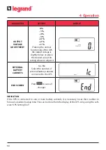
Страница 23: ...lows to adjust it EXTERNAL BATTERY CABINETS 1c 9c Select the number of external battery cabinets connected to the UPS END SCREEN Press to save all changes INDICATION If the UPS is connected to one or more battery cabinets it is necessary to set their number to fore cast a realistic backup time This can be done from the display of the UPS or by using the soft ware UPS Setting Tool 4 Operation ...

Страница 24: ...rmal mode on line double conversion press and simultaneously for approximately three seconds until the buzzer sounds twice The UPS trans fers from normal mode to eco mode During this functioning mode the bypass LED is on Press again and simultaneously until the buzzer sounds twice to return to normal mode 4 8 Emergency Power Off EPO The UPS has an external normally closed contact that can be opene...

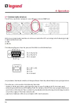
Страница 25: ... 2 D Pin 3 D Pin 4 Ground It is possible to download some free of charge software from the website http www ups legrand com The software can be used for the following functions display of all the operations and diagnostic data in case of problems UPS Communicator setup of special functions UPS Setting Tool For instance the UPS has two programmable out puts for less critical loads These sockets may...

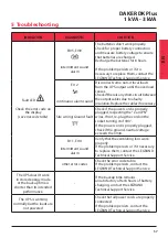
Страница 26: ...ecting the L and N wires If not re plug the cord on the socket turning it of 180 If the power cord is properly plugged check if the ground neutral voltage exceeds the limits Er11 Er14 intermittent sound alarm Verify that the ventilating fans work properly If the problem persists or if it necessary to replace them contact the LEGRAND Technical Support Service other error codes Check the error code ...

Страница 27: ...D Technical Support Service Strange noise or smell Shut down immediately the UPS Disconnect the mains and contact the LEGRAND Technical Support Service The UPS switches off after a total discharge of the batteries The function of autorestart is enabled by default When the mains is available the UPS restarts in normal mode to supply the loads Error code table ERRORCODE MEANING Er05 Battery weak or ...

Страница 28: ...bish is not allowed Apply to the competent agencies in your countries for the proper procedure WARNING A battery may constitute a risk of an electric shock and high short circuit current When working on batteries the prescriptions indicated in chapter 2 are to be adhered to It is important to dismantle the various parts the UPS consists of For these operations Personal Protective Equipment must be...

Отзывы: