Installation Instructions
LSCU
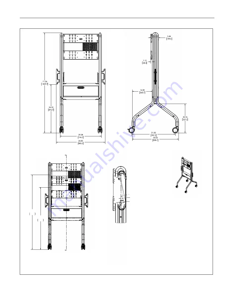
3
DIMENSIONS
MAX
60.96
1548.4
MIN
50.72
1288.4
A
3° TILT
5° TILT
SECTION A-A
SCALE 1 : 5
0 TILT
Страница 1: ...ng Instru es de Instala o Istruzioni di installazione Installatie instructies Instructions d installation Designer Video Cart Spanish Product Description German Product Description Portuguese Product...
Страница 2: ...THE FOLLOWING INSTRUCTIONS CAN RESULT IN SERIOUS PERSONAL INJURY DAMAGE TO EQUIPMENT OR VOIDING OF FACTORY WARRANTY It is the installer s responsibility to make sure all components are properly assem...
Страница 3: ...Installation Instructions LSCU 3 DIMENSIONS MAX 60 96 1548 4 MIN 50 72 1288 4 A 3 TILT 5 TILT SECTION A A SCALE 1 5 0 TILT...
Страница 4: ...LSCU Installation Instructions 4 DIMENSIONS MOUNTING HOLE LOCATIONS...
Страница 5: ...Chave de bocas Chiave a punte aperte Steeksleutel Cl fourche By Hand A mano Von Hand Com a m o A mano Met de hand la main Hex Head Wrench Llave de cabeza hexagonal Sechskantschl ssel Chave de cabe a...
Страница 6: ...rake Q 2 Cart leg w o brake U 2 Coupler assembly J 2 Endcap T 1 Lever lock panel K 2 M 1 Locking plate L 2 Cable cover Side handle X 1 M5 Hardware Bag A 4 M6x12mm B 4 M6x20mm C 4 M6x25mm D 4 M8x12mm M...
Страница 7: ...se on the edge of box See Figure 1 Figure 1 4 Insert coupler assemblies U onto main assembly N lining up the holes on the couplers with the holes on the main assembly N See Figure 2 CAUTION Attachment...
Страница 8: ...tipping it from the top onto its wheels See Figure 6 9 Lock wheels to hold cart in position during installation Figure 6 10 Adjust height to desired height if necessary following steps in ADJUSTMENTS...
Страница 9: ...manufacturer 1 Select correct screws nesting spacers if necessary and universal washers if required from the hardware bag A H and install hardware to back of screen See Figure 8 Figure 8 IMPORTANT Th...
Страница 10: ...e M over top of one of the screws A F to provide necessary stability before tightening screws See Figure 11 5 Tighten all screws A F to make sure display is securely connected See Figure 11 Lever Lock...
Страница 11: ...es to side of cart as desired See Figure 14 Figure 14 3 Route cables through lower holes on cart as desired See Figure 14 Covers Installation NOTE Before installing any cover make sure the handle is i...
Страница 12: ...e frame of cart See Figure 18 3 Lift up and remove faceplate section of mount from outside frame of cart See Figure 18 Figure 18 4 Relocate lower screws to appropriate holes on frame based on desired...
Страница 13: ...nufacturer WARNING Never operate this mounting system if it is damaged Return the mounting system to a service center for examination and repair WARNING RISK OF SERIOUS INJURY OR DEATH Risk of death o...
Страница 14: ...when the cart is not moving by pressing down the locks on wheels See Figure 23 Figure 23 3 Check and tighten the hex nuts on the casters occasionally See Figure 24 These should be checked especially a...
Страница 15: ...Installation Instructions LSCU 15...
Страница 16: ...25 6000 F 877 894 6918 952 894 6918 Europe A Franklinstraat 14 6003 DK Weert Netherlands P 31 0 495 580 852 F 31 0 495 580 845 Asia Pacific A Office No 918 on 9 F Shatin Galleria 18 24 Shan Mei Street...