Archimod HE 240-480®
Installa
tion and main
tenanc
e manual
59
6.4.2 Maintenance procedure for the UPS in maintenance bypass mode
If the power module hot-swap replacement procedure (paragraph 6.4.1) is not applicable, the replacement or the addition
can be made with the UPS in maintenance bypass mode.
This mode is also necessary to perform maintenance or replace parts such as command boards, backplanes, update the
UPS firmware, etc.
CAUTION
During forced and maintenance bypass operations, the load is not protected because it is supplied from the bypass input
line.
CAUTION
The power modules must not be replaced in this mode without adhering scrupulously to the instructions below.
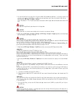
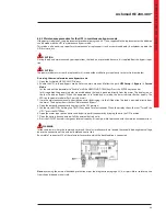
Accessing the manual maintenance bypass mode
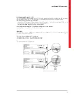
1. Open the Archimod HE 240-480 UPS doors.
2. Enable the UPS in forced bypass mode. Enter the main menu and follow the path
UPS Setup
Bypass
Forced
Mode
.
Set the value of the parameter to “Enable” with the ARROW UP/DOWN keys. Press the ENTER key to confirm.
In this condition the power modules are excluded and the load is powered directly from the mains. The display shows
the text “Forced on Bypass”. When the equipment is in forced bypass mode, the status indicator flashes quickly. The
LEDs on the power modules flash quickly as well.
3. Close the maintenance manual bypass disconnector by bringing it to the ON position. The load is powered directly from
the mains. The display shows the text “Maintenance Bypass”.
4. Open the output disconnector bringing it to the OFF position.
5. Shutdown the UPS by holding the ON/OFF key down for a few seconds. When the display shows the text “Turn off the
UPS?”, press the ENTER key.
6. Open the mains input disconnector and bypass input disconnector by bringing them to the OFF position.
7. Open the battery disconnectors of all the external battery units.
8. Press the ON/OFF key to discharge any internal capacity. It is now possible to proceed with the maintenance operations.
WARNING
Inside the drawer where the command cards and the relay interface card are located there could be dangerous voltage
due to the connection of the external backfeed control line.
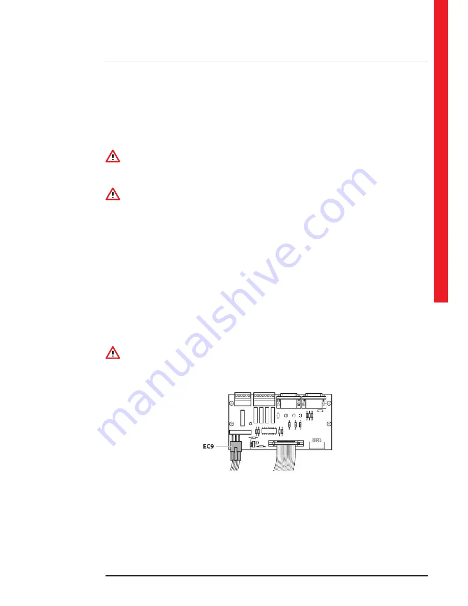
Be careful of connector EC9 of the relay interface card to which the backfeed line is connected.
Note:
by making the external backfeed protection as per the diagram in paragraph 4.2.6, it is possible to isolate the line
from the outside and make it safe.
Содержание Archimod HE 240
Страница 1: ...Archimod HE 240 480 Installation and maintenance manual Item LE09392AA 12 16 01 CT ...
Страница 2: ...2 EN ENGLISH 3 Archimod HE 240 480 ...
Страница 14: ...14 3 Models ...
Страница 15: ...Archimod HE 240 480 Installation and maintenance manual 15 Block diagram ...
Страница 17: ...Archimod HE 240 480 Installation and maintenance manual 17 3 2 Archimod HE 480 all dimensions are in mm ...
Страница 18: ...18 3 Models ...
Страница 19: ...Archimod HE 240 480 Installation and maintenance manual 19 Block diagram ...
Страница 23: ...Archimod HE 240 480 Installation and maintenance manual 23 ...
Страница 24: ...24 4 Installation ...
Страница 25: ...Archimod HE 240 480 Installation and maintenance manual 25 ...
Страница 26: ...26 4 Installation ...
Страница 27: ...Archimod HE 240 480 Installation and maintenance manual 27 ...
Страница 28: ...28 4 Installation ...
Страница 33: ...Archimod HE 240 480 Installation and maintenance manual 33 Archimod HE 240 ...
Страница 36: ...36 Archimod HE 240 4 Installation ...
Страница 41: ...Archimod HE 240 480 Installation and maintenance manual 41 Archimod HE 240 ...
Страница 70: ...70 ...
Страница 71: ...Archimod HE 240 480 Installation and maintenance manual 71 ...


