background image

Automatic transfer switch 

4 226 81

Installa

tion and user manual

19

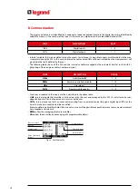
The following table lists shows the available ATS menus: 

CODE MENU

DESCRIPTION

M01

UTILITY

Language, brightness, display pages, etc.

M02

GENERAL

System nominal data

M03

PASSWORD

Password settings

M04

CHANGEOVER

Load changeover settings

M05

LINE 1 CONTROL

Valid limits for voltage line1 (S.Q1)

M06

LINE 2 CONTROL

Valid limits for voltage line 2 (S.Q2)

M07

DIGITAL INPUTS

Programmable digital inputs functions

M08

DIGITAL OUTPUTS

Programmable digital outputs functions

M09

ALARM TABLE

Alarms effect enabling

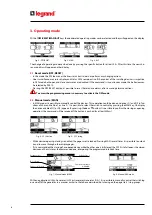
 • The access to the menu/sub-menu modify page is subject to the input of password (if the function is activated).

 • After highlighted the correct menu it is necessary press  

 to show the parameters.

 • Each parameter is shown with code, description and actual setting value.


Fig. 33 - Set-up: parameter selection

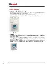
 •  To modify the setting of one parameter, select it and then press 

.

Selected parameter

New value entered

Maximum possible 

setting

Factory default 

setting

Graph bar of the 

value-range

Minimum 

possible setting

Fig. 34 - Set-up: editing page

 • The parameter setting can be modified with + 

 and - 

 keys.  The screen shows the new setting, a graphic bar with 

the setting range, the maximum and minimum values, the previous setting and the factory default.

 • Pr 

 and 

 the value is set to the maximum admitted, while with  

 and - 

 it is set to the minimum. 

N.B. Pressing simultan 

 and - 

 , the setting is set to factory default. 

During the typing of a text string, keys 

 and 

 are used to select the alphanumeric character while + 

 and - 

 are 

used to move the cursor along the text string. 

N.B. Pressing keys 

▲ 

and 

 simultaneously will move the character selection straight to character “A”.

 • Press 

 to go back to the parameter selection. The entered value is saved.

 • Press OFF to save all the settings and to quit the setup menu. The controller executes a reset and returns to normal 

operation. 

 • In “SET-UP” mode, if the user does not press any key for at least 2 minutes, the system leaves automatically and goes 

back to normal viewing without saving the changes done on parameters.

11. Menu

Содержание 4 226 81

Страница 1: ...LINE 1 LINE 2 LOAD IR COM 4 226 82 OFF _ AUT MENU MAN MENU AUT OK RESET Q1 Q2 IEC 60947 6 1 Automatic transfer switch 4 226 81 Installation and user manual Part LE12710AA 01 21 01 GF...

Страница 2: ...IT EN ITALIAN 3 ENGLISH 3 LINE 1 LINE 2 LOAD IR COM 4 226 82 OFF _ AUT MENU MAN MENU AUT OK RESET Q1 Q2 IEC 60947 6 1 2 EN ENGLISH 3 Automatic transfer switch 4 226 81...

Страница 3: ...th do not use abrasives liquids Due of presence of electrical connections the safety standards have to be respected The ATS is supplied with Legrand standard parameters These couldn t respect the nece...

Страница 4: ...OFF RESET 8 3 2 Manual mode MAN 8 3 3 Automatic mode AUT 9 4 Power up 9 5 Main menu 10 6 Password access 11 7 Display pages 12 8 Communication 14 8 1 User Alarms UAx 15 8 2 Counters CNTx 15 9 Keypad...

Страница 5: ...ol line 1 S Q1 menu 24 12 6 Description of Voltage control line 2 S Q2 menu 26 12 7 Description of Programmable inputs menu 27 12 8 Description of Programmable outputs menu 27 12 9 Description of Alar...

Страница 6: ...with App and SW ACU 1 2 Applications To check and to manage lines line to line U U line generator U G or generator generator G G Control of motorized circuit breakers or contactors Control of voltage...

Страница 7: ...line voltage of source 2 S Q2 is within the programmed limits Q1 status LED yellow B If fixed it indicates the open or closed state of the devices Q1 source line 1 If flashing it indicates a mismatch...

Страница 8: ...n could be done on devices Q1 and Q2 in fun ctions of chosen line line 1 or line 2 It is possible to select the switch to control by pressing the MAN key On display the device enabled Q1 or Q2 appears...

Страница 9: ...operating cycles vary both as a function of the type of application Utility Utility Utility Generator Genera tor Generator and as a function of the type of devices used motorized circuit breakers or...

Страница 10: ...the display shows the description of the function Press AUT OK to activate the selected function If some functions are not available the correspondent icon will be disabled shown with light grey colou...

Страница 11: ...of a limited number of setup parameters Advance Level access Lev 3 Complete access to all parameters MENU Password OFF Password ON liv2 liv 3 NO Password Lev 1 Lev 2 Lev 3 M01 X M02 X X M03 X X M04 X...

Страница 12: ...unit Voltage S Q2 Device Q2 S Q2 Contact status device Q2 Operative Mode Frequency Fig 18 L N voltage Voltage Active alarms Fig 19 Alarms status S Q1 Voltage threshold S Q2 Voltage threshold S Q1 Fre...

Страница 13: ...us Digital input status Output status Fig 23 Outputs Fig 25 System info Fig 24 Information page Free user text Note some of the pages listed above may not be displayed if the relevant function is disa...

Страница 14: ...RIPTION RANGE LIMx Limit thresholds 1 4 REMx Remote controlled variables 1 16 UAx User alarms 1 4 CNTx Programmable counters 1 4 Functions associated to the inputs are the 4 described in the above tab...

Страница 15: ...ivated at the same time they are displayed sequentially and their total number is shown on the status bar To reset one alarm that has been programmed with latch use the dedicated command in the comman...

Страница 16: ...y and then press it 5 times then release both keys When the keypad is locked the display shows the word KEYBOARD LOCKED If the keypad isn t locked the display shows the word KEYBOARD UNLOCKED 10 1 Par...

Страница 17: ...ATS to PC generating a file It is also possible to transfer to ATS a file with parameters from SW ACU It is possible to transfer parameters in 2 ways Total transfer all parameters are uploaded on ATS...

Страница 18: ...itch can be configured and consulted also through the front optical port using a USB or WiFi dongle Using this port it is possible to configure and to dialogue with the automatic transfer switch witho...

Страница 19: ...ew value entered Maximum possible setting Factory default setting Graph bar of the value range Minimum possible setting Fig 34 Set up editing page The parameter setting can be modified with and keys T...

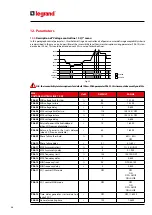
Страница 20: ...phase neutral voltage or both P02 06 N B Nominal voltage set with P02 01 must be referred to phase phase voltage In the followings tables are listed controls that could be done on each line 12 1 Desc...

Страница 21: ...ase of a control parameter won t be respected P02 03 Choosing the type of connection three phase with without neutral two phase or single phase P02 04 Voltage checks performed on concatenated phase vo...

Страница 22: ...c return on priority LINE OFF OFF ON P05 13 Changeover on closing failure only with open feedback OFF OFF 1 2 1 2 P05 14 Minimum voltage coil pulse duration s 1 0 0 1 10 0 P05 15 Delay between minimum...

Страница 23: ...ces are not available at the same time for a time exceeding P5 11 alarm A07 is generated P05 12 If this parameter is enabled after a transfer to the S Q2 restoring to S Q1 does not occur automatically...

Страница 24: ...e 90 70 100 P06 03 MIN voltage delay s 5 0 600 P06 04 MAX voltage limit for trip 115 100 130 OFF P06 05 MAX voltage restore 110 100 130 OFF P06 06 MAX voltage delay s 5 0 600 P06 07 Returnofpowerinthe...

Страница 25: ...e related intervention delay This control may be disabled by setting P06 11 to OFF P06 13 Max frequency intervention threshold it can be disabled P06 14 Max frequency intervention delay P06 15 Min fre...

Страница 26: ...1 source available s 60 1 6000 P07 09 Phase failure threshold 70 60 80 OFF P07 10 Phase failure delay s 0 1 0 1s 30s P07 11 MAX Asymmetry limit 15 1 20 OFF P07 12 MAX Asymmetry delay s 5 0 1 900 P07 1...

Страница 27: ...ee Output functions table P11 n 02 Function index x 1 OFF 1 99 P11 n 03 Normal reverse output NOR NOR REV Note This menu is divided into 15 sections that refer to 7 possible digital outputs OUT1 OUT7...

Страница 28: ...larm properties he ATS has the possibility to manage and generate different types of user alarms User Alarms Uax and for each one can be associated different properties Alarm enabled General enabling...

Страница 29: ...IT NO LCD A01 Timeout Q1 line 1 A02 Timeout Q2 line 2 A03 S Q1 line 1 wrong phase sequence A04 S Q2 line 2 wrong phase sequence A05 Timeout load not powered A06 Emergency A07 Protection intervention Q...

Страница 30: ...05 11 either because both source lines S Q1 and S Q2 were absent or because both Q1 and Q2 remained open A06 Emergency Alarm generated by the opening of the external input with Emergency function Both...

Страница 31: ...Wiring man datory Q1 protection Trip 1 When the contact is closed it informs the ATS of trip status CTR It generates an alarm for Q1 intervention Q2 protection Trip 2 When the contact is closed it inf...

Страница 32: ...UVR opening Q1 before the spring load cycle UVR Coil S Q2 line 2 It controls the UVR opening Q2 before the spring load cycle S Q1 generator control Start Stop remote control of S Q1 generator S Q2 gen...

Страница 33: ...access through serial interface ports Siren OFF It disables the siren Alarms inhibition If enabled it disables the alarms that have the property Inhibit alarms activated Alarms reset It resets the ret...

Страница 34: ...ion the clip in its square hole on the housing side then move it backwards in order to position the hook Fig 37 Mounting Repeat the same operation for the four clips Tighten the fixing screw with a ma...

Страница 35: ...g 38 Rear view CODE DESCRIPTION a Line 1 voltage control S Q1 b Line 2 voltage control S Q2 c OUT1 OUT2 NO Programmable relay d AUX 240VAC power supply e Programmable inputs INP xxx f OUT3 NO NC Progr...

Страница 36: ...ase with or without neutral or balanced three phase system Measuring accuracy Mains and generator voltage 0 25 f s 1digit Real time clock Energy storage Back up capacitors Operating time without suppl...

Страница 37: ...tage Ui 250Vac Rated impulse withstand voltage Uimp 7 3kV Power frequency withstand voltage 3kV Line 1 and Line 2 voltage inputs Rated insulation voltage Ui 480Vac Rated impulse withstand voltage Uimp...

Страница 38: ...uence Z ABDM IEC EN 60068 2 61 Shock resistance 15g IEC EN 60068 2 27 Vibration resistance 0 7g IEC EN 60068 2 6 Connections Terminal type Plug in removable Cable cross section min max 0 2 2 5 mm 24 1...

Страница 39: ...Automatic transfer switch 4 226 81 Installation and user manual 39...

Страница 40: ...rvice BP 30076 87002 LIMOGES CEDEX FRANCE www legrand com Installer stamp Legrand reserves at any time the right to modify the contents of this booklet and to communicate in any form and modality the...

Отзывы: