2
Do not use a switch (with dimmer option) connected
to control a Connected Latching Relay.
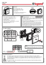
Wiring examples
Wired installation with junction box
Wired installation
Mixed wired and wireless installation
Wireless installation
Tips
: in case of replacement of an old
push button by a wireless control,
isolate wires that are no longer used
The control circuit has integrated power and protection.
9mm
1
OFF
4 mm
PZ1
A load protection circuit breaker with appropriate rating is required
MAX
2x 2.5mm²
6mm²
N, L, Load
:
MAX
2x 1.5mm²
2.5mm²
C1, C2:
MIN : 0.8Nm
MAX : 1.4Nm
C1,C2,
N, L, Load
:
Preparation, connection
Turn off the power
at general
circuit breaker
N (neutral) = blue
L (Line) = everything but blue and green/yellow
Line after contact = usually purple, orange...
C1
C2
N
Load
L
4 121 70
16AX
:
:
I
O OFF
ON
push
buttons
junction
box
push
buttons
C1
C2
N
Load
L
4 121 70
16AX
:
:
I
O OFF
ON
wireless push buttons
push
button
C1
C2
N
Load
L
4 121 70
16AX
:
:
I
O OFF
ON
wireless push buttons
C1
C2
N
Load
L
4 121 70
16AX
:
:
I
O OFF
ON
* : Non-functional indicator lights on push-buttons with indicator lights with connected latching relay
*
*
*
*
*
*
*


