background image

18

Содержание 311112

Страница 1: ...Part LE13511AA 02 22 01 GF 3 111 12 Seismic KitTrimod HE Manuel d installation Installation manual ...

Страница 2: ...2 FR EN IT DE ES FRANÇAIS 3 ENGLISH 11 ITALIANO 19 DEUTSCH 27 SPANISH 35 Seismic Kit Trimod HE ...

Страница 3: ...Seismic Kit TRIMOD HE FR 3 1 Introduction 4 1 1 Contenu 4 2 Comment installer la base 5 2 1 Opération 1 5 2 2 Opération 2 6 2 3 Opération 3 7 2 4 Opération 4 8 Table des matières FR ...

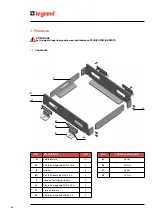
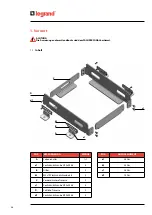
Страница 4: ... b1 B A a1 POS COUPLE DE SERRAGE a1 36 Nm b1 5 5 Nm c1 36 Nm d1 7 5 Nm POS DESCRIPTION QTÉ A Élément latéral 1 1 a1 Vis à tête hexagonale M10x25 8 8 8 B Grille 4 b1 Vis à tête bombée M5x10 8 8 4 C Traverse frontale postérieure 2 c1 Vis à tête hexagonale M10x25 8 8 8 D Traverse latérale 2 d1 Vis à tête hexagonale M6x25 8 8 8 ...

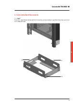
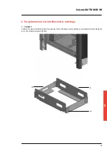
Страница 5: ...E FR 5 2 Comment installer la base 2 1 Opération 1 Retirer les panneaux latéraux à la base de l unité Assembler les éléments latéraux et les éléments frontaux postérieurs à l aide de 4 4 vis à tête hexagonale M10x25 C D c1 ...

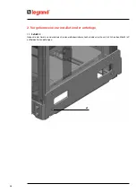
Страница 6: ...6 2 Comment installer la base 2 2 Opération 2 Soulever la machine et installer la base anti sismique en la fixant à l aide de 4 4 vis M6x25 d1 de chaque côté d1 ...

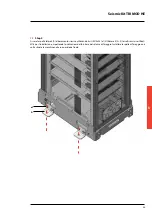
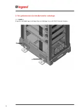
Страница 7: ...a base anti sismique à l aide de 8 vis M10x25 a1 Utiliser 4 2 2 chevilles sismiques certifiés M16 pour l installation en veillant à respecter les indications du fournisseur du système de fixation Installer les soutiens de fixation une fois la machine dans la position finale a1 A ...

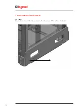
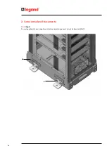
Страница 8: ...8 2 Comment installer la base 2 4 Opération 4 Fixer les grilles de fermeture des évacuations de déplacements à l aide de 8 vis à tête bombée M5x10 b1 B ...

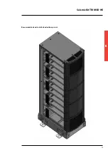
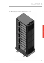
Страница 9: ...Seismic Kit TRIMOD HE FR 9 Comment se présente la base une fois assemblée et installée sous l onduleur ...

Страница 10: ...10 ...

Страница 11: ...Seismic Kit TRIMOD HE EN 11 1 Introduction 12 1 1 Content 12 2 How to install the base 13 2 1 Step 1 13 2 2 Step 2 14 2 3 Step 3 15 2 4 Step 4 16 Contents ...

Страница 12: ...A a1 POS TORQUING MOMENT a1 36 Nm b1 5 5 Nm c1 36 Nm d1 7 5 Nm TAG DESCRIPTION QTY A Lateral mount 1 1 a1 M10x25 class 8 8 hex bolt 8 B Cover 4 b1 M5x10 class 8 8 button head bolt 4 C Front back frame member 2 c1 M10x25 class 8 8 hex bolt 8 D Lateral frame member 2 d1 M6x25 class 8 8 hex bolt 8 1 Introduction ...

Страница 13: ...eismic Kit TRIMOD HE FR EN 13 2 1 Step 1 Remove the lateral panels at the base of the unit Assemble the seismic base fastening the members using 4 4 M10x25 hex head bolts C D c1 2 How to install the base ...

Страница 14: ...14 2 2 Step 2 Lift the unit and install the seismic base fastening it with 4 4 M6x25 hex head screws d1 on both sides d1 2 How to install the base ...

Страница 15: ...al mounts A to the seismic base using 8 M10x25 Hex head screws a1 Use 4 4 M16 certified seismic fasteners to install the base following the indications provided by the supplier Install the lateral mounts once the unit is placed into its final placement a1 A ...

Страница 16: ...16 2 4 Step 4 Place the covers of the lifting points fastening 8 M5x10 button head screws b1 B 2 How to install the base ...

Страница 17: ...Seismic Kit TRIMOD HE EN 17 Base assembled and installed under the ups unit ...

Страница 18: ...18 ...

Страница 19: ...Seismic Kit TRIMOD HE IT 19 1 Premessa 20 1 1 Contenuto 20 2 Come installare il basamento 21 2 1 Step 1 21 2 2 Step 2 22 2 3 Step 3 23 2 4 Step 4 24 Indice ...

Страница 20: ... b1 B A a1 POS COPPIA DI SERRAGGIO a1 36 Nm b1 5 5 Nm c1 36 Nm d1 7 5 Nm POS DESCRIZIONE QTA A Spalla laterale 1 1 a1 Vite testa esagonale M10x25 8 8 8 B Griglia 4 b1 Vite testa bombata M5x10 8 8 4 C Traversa frontale posteriore 2 c1 Vite testa esagonale M10x25 8 8 8 D Traversa laterale 2 d1 Vite testa esagonale M6x25 8 8 8 ...

Страница 21: ...TRIMOD HE IT 21 2 Come installare il basamento 2 1 Step 1 Rimuovere i pannelli laterali alla base dell unità Assemblare gli elementi laterali e quelli frontali posteriori con 4 4 viti testa esagonale M10x25 C D c1 ...

Страница 22: ...22 2 Come installare il basamento 2 2 Step 2 Sollevare la macchina e installare la base antisismica fissandola con viti 4 4 M6x25 d1 da entrambi i lati d1 ...

Страница 23: ...amento sismico utilizzando 8 viti M10x25 a1 Utilizzare 4 2 2 tasselli sismici certificati M16 per l installazione rispettando le indicazioni del fornitore del sistema di fissaggio Installare le spalle di fissaggio una volta situata la macchina nella sua posizione finale a1 A ...

Страница 24: ...24 2 Come installare il basamento 2 4 Step 4 Fissare le griglie di chiusura degli scarichi di movimentazione con 8 viti a testa bombata M5x10 b1 B ...

Страница 25: ...Seismic Kit TRIMOD HE IT 25 Come si presenta il basamento assemblato e installato sotto all unità UPS ...

Страница 26: ...26 ...

Страница 27: ...Seismic Kit TRIMOD HE 27 DE 1 Vorwort 28 1 1 Inhalt 28 2 Vorgehensweise zur installation der unterlage 29 2 1 Schritt 1 29 2 2 Schritt 2 30 2 3 Schritt 3 31 2 4 Schritt 4 32 Inhaltsverzeichnis ...

Страница 28: ... b1 B A a1 POS ANZUGSMOMENT a1 36 Nm b1 5 5 Nm c1 36 Nm d1 7 5 Nm POS BESCHREIBUNG MENGE A Seitenschulter 1 1 a1 Sechskantschraube M10x25 8 8 8 B Gitter 4 b1 M5x10 Flachrundschraube 8 8 4 C Vordere hintere Traverse 2 c1 Sechskantschraube M10x25 8 8 8 D Seitliche Traverse 2 d1 Sechskantschraube M10x25 8 8 8 ...

Страница 29: ... 29 2 Vorgehensweise zur installation der unterlage 2 1 Schritt 1 Entfernen Sie die Seitentafeln an der Unterseite des Geräts Montieren Sie die seitlichen und vorderen hinteren Elemente mit 4 4 Sechskantschrauben M10x25 C D c1 ...

Страница 30: ... 2 Vorgehensweise zur installation der unterlage 2 2 Schritt 2 Heben Sie das Gerät an und montieren Sie den erdbebensicheren Sockel indem Sie ihn mit 4 4 Schrauben M6x25 d1 auf beiden Seiten befestigen d1 ...

Страница 31: ...M10x25 a1 an der seismischen Basis Verwenden Sie für die Installation 4 2 2 M16 zertifizierte seismische Dübel und befolgen Sie dabei die Anweisungen des Lieferanten des Befestigungssystems Wenn das Gerät in seiner endgültigen Position befindet aufgestellt ist bringen Sie die Befestigungsschultern an a1 A ...

Страница 32: ...32 2 Vorgehensweise zur installation der unterlage 2 4 Schritt 4 Bringen Sie die Abdeckungen der Hebepunkte an und befestigen Sie sie mit 8 M5x10 Flachrundschrauben b1 B ...

Страница 33: ...Seismic Kit TRIMOD HE 33 DE An sicht der fertig zusammengebauten und unter der usv einheit installierten unterlage ...

Страница 34: ...34 ...

Страница 35: ...Seismic Kit TRIMOD HE ES 35 1 Introducciòn 36 1 1 Contenido 36 2 Cómo instalar la base 37 2 1 Paso 1 37 2 2 Paso 2 38 2 3 Paso 3 39 2 4 Paso 4 40 Indice ...

Страница 36: ...A a1 POS PAR DE APRIETE a1 36 Nm b1 5 5 Nm c1 36 Nm d1 7 5 Nm POS DESCRIPCIÓN QTÉ A Soporte lateral 1 1 a1 Tornillo de cabeza hexagonal M10x25 8 8 8 B Rejilla 4 b1 Tornillo de cabeza convexa M5x10 8 8 4 C Travesaño delantero trasero 2 c1 Tornillo de cabeza hexagonal M10x25 8 8 8 D Travesaño lateral 2 d1 Tornillo de cabeza hexagonal M6x25 8 8 8 ...

Страница 37: ...RIMOD HE ES 37 2 Cómo instalar la base 2 1 Paso 1 Retirar los paneles laterales de la base de la unidad Ensamblar los elementos laterales y los delanteros traseros con 4 4 tornillos de cabeza hexagonal M10x25 C D c1 ...

Страница 38: ...38 2 Cómo instalar la base 2 2 Paso 2 Elevar la máquina e instalar la base sísmica fijándola con tornillos 4 4 M6x25 d1 por ambos lados d1 ...

Страница 39: ... base sísmica utilizando 8 tornillos M10x25 a1 Utilizar 4 2 2 tacos sísmicos certificados M16 para la instalación siguiendo las indicaciones del proveedor del sistema de fijación Instalar los soportes de fijación tras haber situado la máquina en su posición final a1 A ...

Страница 40: ...40 2 Cómo instalar la base 2 4 Paso 4 Fijar las rejillas de cierre de los puntos de manipulación con 8 tornillos de cabeza convexa M5x10 b1 B ...

Страница 41: ...Seismic Kit TRIMOD HE ES 41 Cómo se presenta la base ensamblada e instalada bajo la unidad SAI ...

Страница 42: ...42 ...

Страница 43: ...Seismic Kit TRIMOD HE 43 ...

Страница 44: ...ime the right to modify the contents of this booklet and to communicate in any form and modality the changes brought to the same Timbro installatoreInstaller stamp LEGRAND Pro and Consumer Service BP 30076 87002 LIMOGES CEDEX FRANCE www legrand com Legrand se réserve le droit de modifier à tout moment le contenu de cet imprimé et de communiquer sous n importe quelle forme et modalité les changemen...

Отзывы: