background image

7

PPR

REEPPA

AR

RIIN

NG

G TTH

HEE A

APPPPLLIIA

AN

NC

CEE

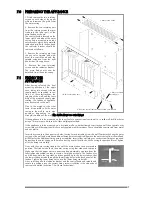
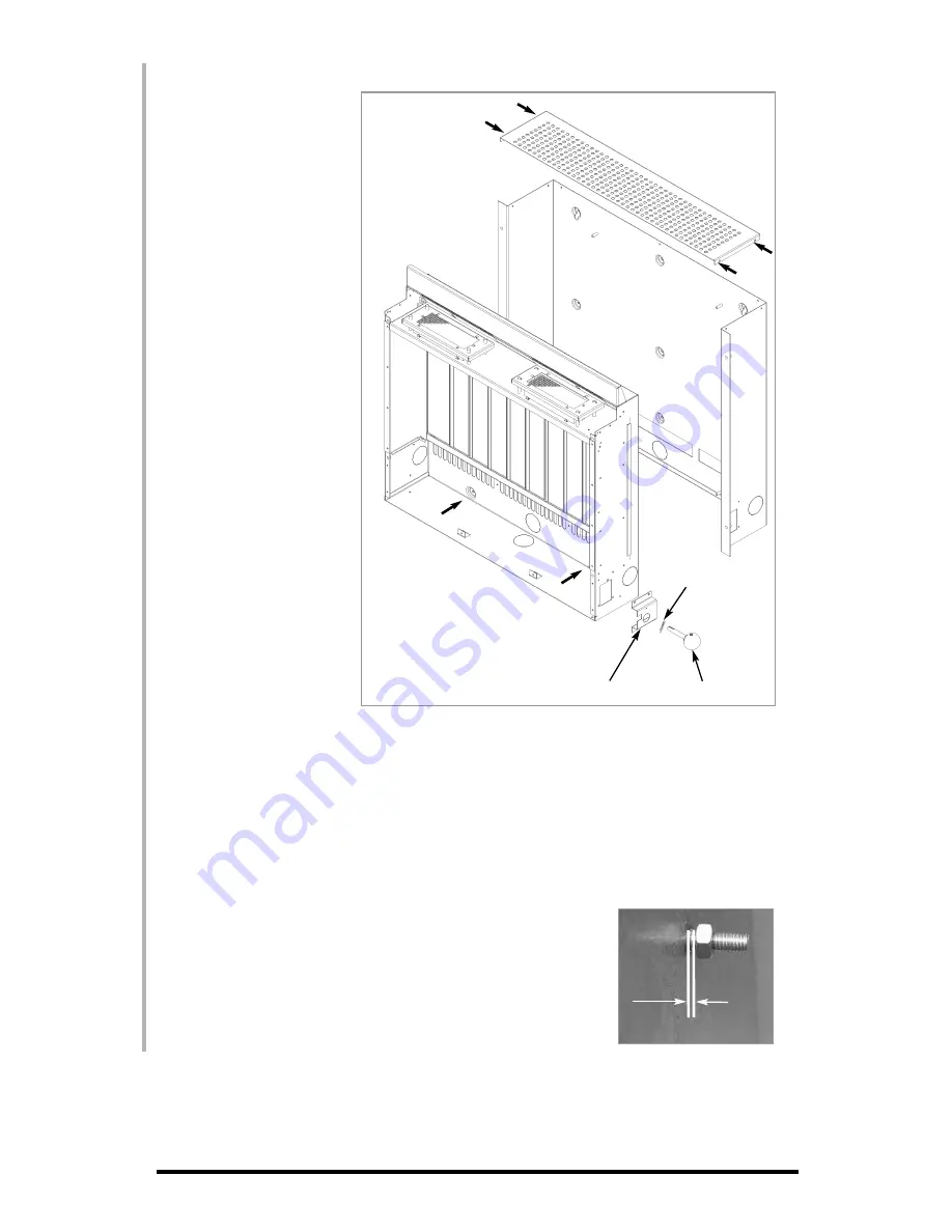
1. Firstly remove the two retaining

screws on each side of the upper

grille and remove the grille from

the outer casing. 

2. Remove the two retaining nuts

from the retaining studs that pro-

trude into the lower part of the

main firebox as shown.

The control knob is located on the

lower right hand side of the outer

casing, and is mounted in an indi-

cator bracket, which has a metallic

indication ‘pip’. Both the knob and

the indicator bracket should be

removed as follows; 

3. Remove the retaining pin from

the gas valve spindle and with-

draw the control knob and the

spindle extension from the right

hand side of the appliance. 

4. Remove the four retaining

screws and the indicator bracket.

The main firebox may now be

detached from the outer casing.

FFIIXXIIN

NG

G TTH

HEE

A

APPPPLLIIA

AN

NC

CEE

After having selected the final

mounting position of the appli-

ance, taking into account the site

requirements as specified in sec-

tion 4 of these instructions, the

integrity of the wall, and the feasi-

bility of the proposed supply  pipe

routing, the firebox of appliance

may be secured to the wall. 

Due to the weight of the front

facia, it is possible to fix the outer

casing to the wall in up to nine

positions, depending on the

strength/condition of the wall. IIff iinn ddoouubbtt aallw

waayyss uussee eexxttrraa ffiixxiinnggss!!

If the appliance is to be mounted on the inner leaf of a conventional cavity wall, or a solid wall, drill four holes

using a 7mm masonry bit. Insert the fibre wallplugs provided.

If the appliance is to be mounted on a dry lined wall or a timber framed construction wall then special cavity

screw fixings will be required which are not supplied with this product. These should be constructed from metal

and not plastic.

Insert the screws into the upper two holes, leaving 5mm protruding from the wall. Temporarily hang the outer

casing on the wall, and mark any additional fixing points as required. Remove the outer casing from the wall and

drill holes for the additional fixing points as required. Insert either wall plugs or cavity screw fixings as required.

Re-position the outer casing on the wall and using a spirit level to check the casing is square and level, tighten

all of the fixing screws fully.

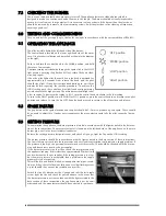
Now, with the outer casing fixed to the wall, the main firebox can be secured in

position. The firebox is held on the outer casing using four studs and four nuts.

Make sure that the upper nuts are un-screwed approximately one turn from the

fully tightened position in order to create a 2mm gap as shown. The firebox may

now be hung onto the top studs, and then pushed onto the lower studs so that

the lower studs protrude through the lower fixing holes in the back panel of the

firebox. Tighten the lower fixing nuts on to the lower fixing studs fully.

Next, re-fit the grille, the indicator bracket and the control knob and spindle, and

secure in position using the correct fixing screws (re-fitting is the opposite of

removal as detailed in section 7.0 of these instructions).

77..00

1. Remove the Grille

2. Remove retaining nuts

3. Remove spindle
retaining pin

4. Remove control indicator bracket and control knob

77..11

2mm

Содержание ECO 1000

Страница 1: ... the end user when the installation is complete This is an official requirement and is the responsibility of the fitter of this appliance Having installed the appliance the installer should take the necessary steps to ensure that the user fully understands how to operate the appliance and is also made aware of the fire s basic cleaning and maintenance requirements ...

Страница 2: ...e circulation of air and ensure the correct operation of the fire This volume may include adjacent spaces but these spaces must not be separated by a door In order to convert from cubic feet ft3 to cubic metres m3 divide the room volume in ft3 by 35 3 This appliance is intended as a secondary source of heat only and should not be used in a room without some form of background heating present The a...

Страница 3: ...ace A minimum of 100cm2 15 5 in2 purpose provided ventilation is required for this appliance an openable window or louvre is also required To reduce the pos sibility of draughts entering the room via the air vent we recommend the use of Black Hole or Vortex type vents featuring internal baffles Consult ALL instructions before installation and use of this appliance This appliance is free from any a...

Страница 4: ... r re ec ce es ss s a an ny y p pa ar rt t o of f t th he e a ap pp pl li ia an nc ce e i in nt to o t th he e w wa al ll l This Appliance may be installed in any room in a home however there are exceptions and the appliance may not be used in the following rooms Bedrooms or areas which are mainly used for sleeping Bathrooms or areas where large amounts of steam are likely to be generated Installa...

Страница 5: ...e wall above the appliance The appliance is designed to be wall mounted alone and not in conjunction with any type of combustible fire surround No combustible shelves should be positioned on the wall above the appli ance It should be established that any mirrors or picture frames etc to be positioned on the wall above the appliance are able to withstand prolonged exposure to moderate heat and mois...

Страница 6: ...e firebox Select the most appropriate entry point and knock out the relevant holes in both the firebox and the outer casing No more than 1 5m of 8mm diameter pipe must be used to avoid unnecessary pressure drops If a concealed gas connection is to be made the supply pipe should always be sleeved through walls and floors using the shortest possible route For concealed supply pipe routing pipes must...

Страница 7: ...l drill four holes using a 7mm masonry bit Insert the fibre wallplugs provided If the appliance is to be mounted on a dry lined wall or a timber framed construction wall then special cavity screw fixings will be required which are not supplied with this product These should be constructed from metal and not plastic Insert the screws into the upper two holes leaving 5mm protruding from the wall Tem...

Страница 8: ... the knob pressed in return to the off position and release S SP PA AR RK K F FA AI IL LU UR RE E The gap between the spark electrode and the pilot should be 3 5mm to produce a good spark There should be no need to adjust this If under any circumstances the piezo electric spark fails the pilot cannot be lit man ually S SE ET TT TI IN NG G P PR RE ES SS SU UR RE E To commission the appliance the bu...

Страница 9: ...a guard be used for the protection of the young pets the eld erly and the infirm S SE ER RV VI IC CI IN NG G Isolate the fire from the gas supply Ensure that the fire is fully cold before attempting service A suggested pro cedure for servicing is detailed below 1 Lay out the dustsheet and tools 2 Remove the facia section Removal is the reverse of fitting as detailed in section 8 4 3 Remove the gla...

Страница 10: ... not damage or try to dismantle the pilot injector The unit is factory set and the only check necessary is to ensure the spark gap is correct See specifications for gas setting N NE EV VE ER R M MO OD DI IF FY Y O OR R B BE EN ND D T TH HE E T TH HE ER RM MO OC CO OU UP PL LE E T TO O M MA AK KE E T TH HE E P PI IL LO OT T S ST TA AY Y A AL LI IG GH HT T If the pilot will not stay lit there is a p...

Страница 11: ... removed be unscrewing the retaining nuts securing the clamping plate Remove the catalyst and its seal and discard Refit a new catalyst and seals in reverse order ensure the catalyst and door have good seals T TE ES ST TI IN NG G F FO OR R F FI IR RE EB BO OX X L LE EA AK KA AG GE E Appliances that are several years old or have been extensively dismantled should be checked for soundness It is impo...

Страница 12: ...ing to metalwork under tray realign HT lead F Fi ir re e r ru un ns s f fo or r a a t ti im me e a an nd d t th he en n c cu ut ts s o of ff f Loose or faulty thermocouple rectify Blocked pilot clean out Dirt or lint in pilot aeration hole or on the lint gauze clean thoroughly If the pilot will not stay lit there is a problem with dirt the gas sup ply or the thermocouple needs replacement Modifica...

Страница 13: ...able fireguard conform ing to BS 8423 is used especially where young children pets the elderly or infirm are concerned The manufacturer of this appliance considers all surfaces as working surfaces with the exception of the control knob Combustible items such as flooring and furniture and soft wall coverings such as blown vinyl or embossed paper low temperature surrounds etc may discolour if fitted...

Страница 14: ...ack panel of the appliance The wall must be structurally sound and constructed from a material capable of withstanding moderate heat Finished plaster conventional wall paper and dry lined plasterboard are examples of suitable materials Materials such as flock blown vinyl and embossed paper which are sensitive to even small amounts of heat should be avoided as scorching and or dis colouration may o...

Страница 15: ...for a few seconds Continue turning anti clockwise through the spark click to the PILOT light position ensuring the pilot has lit If not return the knob clock wise and repeat When the pilot lights after the spark keep the knob depressed for approximately ten seconds Now release the knob and the pilot should stay alight If the pilot is extinguished during use wait three minutes before repeating the ...

Страница 16: ... the direction of the grain S SE ER RV VI IC CI IN NG G The appliance should be checked on an annual basis to ensure it is working safely and that there is no exces sive build up of soot The frequency of service will depend on usage but MUST be carried out at least once annually Servicing must be carried out by a competent person such as a CORGI registered installer Cleaning of the coals may be ca...

Отзывы: