background image

Encrypted Digital Wireless System 

PIN 5

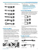
 - 40 k high impedance, line level input for 

tape decks, mixer outputs, musical instruments, etc. 

PIN 

1

SHIELD 

AUDIO 

BIAS 

3 WIRE ELECTRET MIC 

POSITIVE BIAS 

2

TA5F 

PLUG 

PIN 

SHIELD 

2 WIRE ELECTRET MIC 

AUDIO 

POSITIVE BIAS 

2

TA5F 

PLUG 

PIN 

1

SHIELD 

BIAS 

AUDIO 

3 WIRE ELECTRET MIC 

NEGATIVE BIAS 

2

TA5F 

PLUG 

PIN 

SHIELD 

AUDIO 

2 WIRE ELECTRET MIC 

NEGATIVE BIAS 

2

TA5F 

PLUG 

SLEEVE 

PIN 

SHIELD 

2

AUDIO 

TIP 

LINE LEVEL 

2

RCA or 1/4 " PLUG 

TA5F 

PLUG 

1

PIN 

PIN 

SHIELD 

DYNAMIC 

Dynamic  LO Z mic or electret with 

2

TA5F 

manufacturer’s power supply. 

MIC LEVEL 

PLUG 

Wiring Hookups for Different Sources (UM700) 

RF Bypassing (UM700) 

Some mics require RF protection to keep the transmit­
ter signal from affecting the capsule, even though the 
transmitter input circuitry is already RF bypassed (see 
5-Pin Input Jack Wiring schematic diagram ). 

If the mic is wired as directed, and you are having 
difficulty with squealing, high noise, or poor frequency 
response, RF is likely to be the cause. 

The best RF protection is accomplished by installing 
330 pF bypass capacitors at the mic capsule.  If this is 
not possible, or if you are still having problems, capaci­
tors can be installed on the mic wires inside the TA5F 
connector housing. 

The 330 pF capacitors are available from Lectrosonics. 

2 WIRE MIC 

3 WIRE MIC 

Please specify the part number for the desired lead style. 

Leaded capacitors: 

P/N 15117 

Leadless capacitors: 

P/N SCC330P 

Note: The M150-7005P microphone is bypassed 
correctly for use with the UM700 Encrypted Digital 
Transmitter and is the recommended lavaliere 
microphone for the 700 Series wireless 
microphone system. 

Line Level Signals (UM700) 

The normal hookup for line level signals provides 40 dB 
of attenuation allowing signal levels up to 30 V to be 
applied without limiting.  The normal hookup configura­
tion can be modified for situations that require higher 
levels of headroom, or lower levels of attenuation. 

PIN 

SHIELD (GND) 

Normal Hookup 

2

AUDIO 

TA5F 

PLUG 

PIN

SHIELD (GND) 

More Headroom 

2

4

100k 

AUDIO 

TA5F 

PLUG 

PIN 

SHIELD (GND) 

Lower Line Level 

Hookup 

2

4

AUDIO 

TA5F 

PLUG 

Normal hookup connects the Signal Hot (Audio) to pin 
5, Signal Gnd (Shield) to pin 1, and both pins 3 and 4 
jumped to pin 1. 

If even more headroom is required, insert a 100 k 
resistor in series with pin 5 (Audio).  Put this resistor 
inside the TA5F connector to minimize noise pickup. 

For situations where lower than normal line levels (less 
than 1 V) are expected, use the Lower Line Level Hook 
Up:  Signal Hot (Audio) to pin 5, Signal Gnd (Shield) to 
pin 1, and pin 4 jumpered to pin 1.  This configuration 
provides 20 dB attenuation allowing signal levels up to 3 
V to be applied without limiting. 

Encryption Key Cables 

Each digitally encrypted transmitter uses a different 
encryption key cable.  The configuration of these cables 
is listed below. 

S

LEEVE 

S

LEEVE 

TIP 

Mini Pl

u

TIP 

3

.5 mm Pl

u

Preferred locations for bypass capacitors 

CAPSULE 

CAPSULE 

SHIELD 

AUDIO 

SHIELD 

AUDIO 

BIAS 

UT700KEY CABLE 

SLEEVE 

SHIELD 

2

1

DATA 

2

1

5

PIN 

TIP 

TA5F 

Mini Plug 

4

CONNECTOR 

TA5F

5

TA5F 

CONNECTOR

Alternate locations for bypass capacitors 

UM700KEY CABLE 

PLUG

Rio Rancho, NM 

25


Содержание UDR700

Страница 1: ...700 Series INSTRUCTION MANUAL Encrypted Digital UHF Wireless System Includes UDR700 UM700 UT700 Rio Rancho NM USA www lectrosonics com Fill in for your records Serial Number Purchase Date ...

Страница 2: ...ption System 9 Level 1 9 Level 2 9 Level 3 9 UDR700 Controls and Functions 11 UDR700 Front Panel 11 RF Level Indicator 11 Transmitter Audio Level 11 Information and Status Display 11 Menu Button 11 Select Up Down Buttons 11 Rota Versity Switch 11 Antenna Phase Combining Indicator 11 Power Switch 11 Security Jack 11 Audio Monitor Level 11 Audio Monitor Jack 11 UDR700 Rear Panel 12 AC Power Supply 1...

Страница 3: ...17 System Installation and Operating Instructions 19 System Setup 19 Changing the Security Level 22 Setting the Encryption Key 22 Protecting the Encryption Key 23 UT700 Vari Mic Controls 23 Bass Mid Treble LO MID HI 23 Preamp Level Control 24 Bass Filter 24 5 Pin Input Jack Wiring UM700 24 RF Bypassing UM700 25 Line Level Signals UM700 25 Encryption Key Cables 25 Troubleshooting 27 Power Problems ...

Страница 4: ...UDR700 UM700 UT700 LECTROSONICS INC 4 ...

Страница 5: ...to recover the original audio signal present in the transmitter UDR700 Encrypted Digital Receiver Rota Versity Reception The UDR700 receiver uses a proprietary technique to implement a unique and very effective type of diversity reception called Rota VersityTM Rota versity is a microprocessor controlled antenna phase matching technique The UDR700 uses a four way phase shifter to combine the power ...

Страница 6: ... audio level in calibrated 5 dB steps ensuring the signal to noise ratio of the receiver remains the same at all output levels selected by the rear panel control Encrypted Digital Transmitters Two encrypted digital transmitters are offered a belt pack unit and a hand held unit Although their physical packages differ internally they are essentially the same The major difference is the microphone in...

Страница 7: ...revent rattle as the unit is handled UT700 Block Diagram Mic Frequency Agility 700 Series wireless systems are currently available in four different blocks of 256 frequencies each from 562 200 to 665 500 MHz Note Frequencies between 608 000 MHz to 614 000 MHz are reserved and not available for commercial use Each of these blocks is preset at the factory and provides 256 selectable frequencies in 1...

Страница 8: ...tDiversity SmartDiversity is a microprocessor controlled tech nique that automatically analyzes audio content and RF levels to determine optimum timing for the switching activity Active analog antenna phase switching tech niques use both antennas at the same time with 180 degree phase switching to help keep the received signals in phase and minimize dropouts When the overall RF signal strength qui...

Страница 9: ...te effective security Level 1 is the default security level Level 2 Security Level 2 offers much greater encryption strength at the cost of slightly less intuitive operation In Level 2 the scrambling sequence never repeats i e the PRNG is free running so the receiver must be on and ready to receive when the transmitter is first switched on Some signal loss is tolerated but if the transmitter shoul...

Страница 10: ...UDR700 UM700 UT700 LECTROSONICS INC 10 ...

Страница 11: ... or tuning group transmitter Frequency Select Switch setting TV channel transmitter battery level and system locked unlocked status Menu Button The MENU button steps the Information and Status Display through six different displays used for setup and operation See Information and Status Display Menus and Functions and Installation and Operating Instructions Select Up Down Buttons The SELECT Up Dow...

Страница 12: ... ground loop Note Ground loops can occur when the analog audio output is connected to remote equipment powered from a different AC main supply Phase 0 180 The PHASE 0 180 switch reverses the polarity of the analog audio output signal Digital Audio Output AES 3id A BNC connector providing a digital audio output signal conforming to the AES 3id standard Antenna Jacks These are standard 50 Ohm BNC te...

Страница 13: ...r battery voltage This makes it easier to avoid occupied UHF TV channels in the geographical area of operation 9 1 4 7 T V 0 0 1 8 6 6 Group Tuning Menu The Group Tuning menu displays the current group the three groups are designated A B and C and the selected frequency within that group The Transmitter Frequency Select Switch settings are shown at right as on the other tuning menus G R P A C H A ...

Страница 14: ...ss than that time to determine when the battery needs to be replaced A weak battery will sometimes cause the Power LED to glow green immediately after the unit is powered up but will soon discharge to the point where the LED will go red flicker red or shut off completely much like a flashlight with dead batteries If the lamp fails to light the battery should be replaced Frequency Select Switches L...

Страница 15: ... low noise situations such as a motion picture production set indoors where environmental noise is minimal the control can be rotated counter clockwise to permit low frequency audio to be captured The Belt Clip The belt clip may be removed for special applications by removing the Belt Clip Attachement Screw WARNING USE ONLY THE SCREW THAT IS SUPPLIED The circuitry is tightly packed into this unit ...

Страница 16: ...at the batteries will run the unit and in the future use somewhat less than that time to determine when the battery needs to be replaced When the unit is first turned on the Power LED also blinks a code to indicate the current Security Level Level 1 One blink Level 2 Two blinks Level 3 Three blinks Modulation LEDs 10 20 Fine Coarse Frequency Switches Audio Level Control Hiding the Power LED This u...

Страница 17: ...ttery UT700 Battery Installation Caution The transmitter is designed for a standard alkaline or lithium 9 volt battery It is important that you use an alkaline or lithium battery for longest life Standard zinc carbon batteries marked heavy duty or long lasting are not adequate Ni cad rechargeable batteries will only provide 1 5 hours of operation or less and will run down quite abruptly Alkaline b...

Страница 18: ...UDR700 UM700 UT700 LECTROSONICS INC 18 ...

Страница 19: ...or the receiver end and wire it according to the diagram below Pin 4 is positive and Pin 1 is ground Antenna Input BNC Connectors AC Power Input Jack 90 to 240 VAC 50 60 Hz Audio Monitor Level Counterclockwise External Power Connector 11 17 VDC PHASE Switch 0 Analog Audio Output Control 5 Connect the Audio Output XLR jack to your mixer input Pins 2 and 3 of the XLR jack are HI and LO and can be re...

Страница 20: ...ery Compartment Coarse Fine Frequency Select Switches UM700 9 Determine the security level required See The 700 Series Encryption System 10 Turn the UDR700 Off then press and hold the SELECT Down button while turning the UDR700 back on The display will show the current security level The default is Level 1 11 Use the SELECT Up or Down buttons to choose a new security level then press the MENU butt...

Страница 21: ... so check this adjustment as each new person uses the system If several different people will be using the transmitter and there is not time to make the adjustment for each individual adjust it for the loudest voice Note In the UT700 if you find that the Audio Level control is set to minimum and the 20 LED still glows green then adjust the preamp level control located under the microphone wind scr...

Страница 22: ... key In Security Level 3 only one transmitter may receive the encryption key See The 700 Series Encryption System 1 To set a new encryption key press the MENU button to scroll through the menus until the SECU RITY MENU is displayed in the Information and Status Display Press MENU once more to enter the Key Generation Menu MAKE NEW KEY will be displayed in the Information and Status Display with an...

Страница 23: ...en in place The VariMic head includes adjustments for the microphone element s Bass Midrange and Treble response There is also an attenuation adjustment to provide up to 15 dB of additional headroom if needed These controls can be accessed by removing the windscreen To remove the windscreen grasp the body of the transmitter in one hand and the windscreen in the other hand Unscrew the windscreen co...

Страница 24: ...wireless microphone the electronics that will be overdriven are right in the wireless microphone Filtering at the control board is much too late To solve this problem the VariMic has a low frequency filter that is so sharp that it can remove low frequency noise without affecting any wanted vocals It consists of a 36 dB per octave filter circuit to sharply remove low frequency noise below 75 Hz wit...

Страница 25: ...he M150 7005P microphone is bypassed correctly for use with the UM700 Encrypted Digital Transmitter and is the recommended lavaliere microphone for the 700 Series wireless microphone system Line Level Signals UM700 The normal hookup for line level signals provides 40 dB of attenuation allowing signal levels up to 30 V to be applied without limiting The normal hookup configura tion can be modified ...

Страница 26: ...UDR700 UM700 UT700 LECTROSONICS INC 26 ...

Страница 27: ...rds Battery is dead or too low to be used No Modulation LEDs Battery dead or in backwards Check Power LED Audio Level Control turned all the way down Mic capsule is damaged or malfunctioning Contact the factory for repair RF Problems Antenna Phase Combining Indicator on UDR700 has three LEDs glowing but never moves The ROTA VERSITY switch is set to the A or B position using only one antenna instea...

Страница 28: ... If the noise remains then turn the power off at the transmitter and see if it remains If the noise is still present then the problem is not in the transmitter If noise is still present when the transmitter is turned off try lowering the audio output level on the receiver rear panel and see if the noise lowers correspondingly If the noise remains the problem is not in the receiver Receiver output ...

Страница 29: ...one that works fine on an FM system might not work on a 700 series system To protect the microphone from RF it is necessary to bypass it effectively at both ends of the cable Ensure that bypass capacitors are installed inside the connector housing If the mic is not sufficiently bypassed at the capsule it may be necessary to use a different type of microphone The UM700 transmitter is shipped with a...

Страница 30: ...teps at 20 10 0 10 dB with green and red indications Low frequency roll off adjustment 18 dB octave 35 Hz to 150 Hz Controls 2 position ON OFF slide switch Front panel knob adjusts audio gain Recessed control on side panel adjusts low frequency rolloff Rotary switches on side panel adjust transmitter frequency Audio Input Jack Switchcraft 5 pin locking TA5M Note The M150 7005P microphone is bypass...

Страница 31: ...Encrypted Digital Wireless System Rio Rancho NM 31 ...

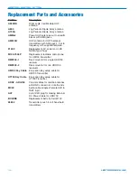
Страница 32: ...e Plug M150 7005P Replacement lavaliere microphone for UM700 transmitter RMP200 1 Rack mount kit for single UDR700 receiver RMP200 2 Rack mount kit for two UDR700 receivers UM700 Key Cable Encryption Key setup cable for UM700 Transmitter UT700 Key Cable Encryption Key setup cable for UT700 Tranmitter ARG2 ARG100 Coaxial cables for remote antennas with BNC connectors on both ends MC40 Audio cable a...

Страница 33: ...ere is a charge for an exact quotation We will be happy to quote approximate charges by phone for out of warranty repairs Returning Units for Repair For timely service please follow the steps below A DO NOT return equipment to the factory for repair without first contacting us by letter or by phone We need to know the nature of the problem the model number and the serial number of the equipment We...

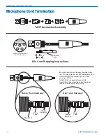
Страница 34: ...re touches the metal crimp tab This helps prevent any AM component of the transmitter signal from entering the mic and causing a whine Note that this is opposite from our VHF transmitter wiring where the shield should not touch any metal part of the housing Shield Wire Crimp Tabs Rubber Insulation Crimp Tabs Rubber Insulation This is the correct way Don t do it this way LECTROSONICS INC 34 ...

Страница 35: ...Encrypted Digital Wireless System Rio Rancho NM 35 ...

Страница 36: ...horized dealer shipping costs prepaid within one year from the date of purchase This Limited Warranty is governed by the laws of the State of New Mexico It states the entire liablility of Lectrosonics Inc and the entire remedy of the purchaser for any breach of warranty as outlined above NEITHER LECTROSONICS INC NOR ANYONE INVOLVED IN THE PRODUCTION OR DELIVERY OF THE EQUIPMENT SHALL BE LIABLE FOR...

Отзывы: