Lectrosonics SPNTrio Скачать руководство пользователя страница 13

Installation and Startup Guide

Rio Rancho, NM

13

Firmware Update 

Procedure

1) Install ASPEN software. See the previous page for 

an example of the installation procedure.

2) Launch the software. After the panel opens, click on 

File > Update

. The 

Update Wizard

 screen will open 

to confirm that the software is ready for a firmware 

update, with instructions on connecting and config-

uring the processor.

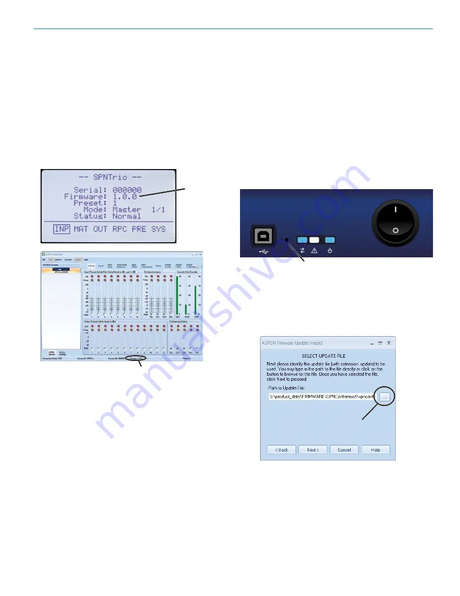
3) On the processor, hold the recessed pushbutton 

switch in with a pen or paper clip and turn on the 

power to the processor. The unit will boot into the 

Firmware Update...

 mode and the white Alert LED 

on the processor front panel will glow.

Recessed pushbutton for firmware updates

4) Connect the processor to the computer with the 

USB cable. When the USB connection is confirmed 

(typically with a beep sound on the computer), 

continue by following the on screen prompts in the 

Update Wizard

.

5) When prompted, use the “Browse” button to point at 

the firmware update file and click 

Next

 to continue.


Browse 

button

6) Do not disturb the USB cable connection during the 

update process. The firmware update takes up to 

15 minutes to complete. Be sure the computer does 

not “Time Out” during the update process.

7) When the update is complete, click 

Finish

 to exit the 

Update Wizard.

8) Cycle the power on the processor to restart using 

the updated firmware.

Software and  

Firmware Updates

Check for the latest versions of the control panel soft-

ware and to see that the hardware includes the latest 

firmware.
ASPEN models with a front panel LCD will display the 

firmware version on the LCD and in the control panel 

GUI after the software is installed. Other models display 

the firmware version in the GUI only. Firmware updates 

require that the ASPEN software be installed to enable 

a connection and use the update utility included in the 

software.

Firmware 

version

Firmware version

Obtaining Updates

The latest versions of software and firmware are pro-

vided on the disk supplied with the unit and download-

able from:
http://www.gnarlywireless.com/AspenSupport/
Link on home page:  http://www.lectrosonics.com

ASPEN Software:  

Uninstall any previous version be-

fore installing an updated version.
Downloaded files arrive in a .zip format. Extract the files 

to a folder on your local drive and then run “setup.exe” 

to install the program.

Firmware Updates:  

Downloaded files arrive in a single 

.zip file with the model number and version indicated by 

the filename.
Extract the file to a folder on your local drive. The result-

ing filename will indicate the model number and ver-

sion, followed by the extension “.update.”

Содержание SPNTrio

Страница 1: ...Date SPNTrio Digital Conference Interface INSTALLATION and STARTUP GUIDE Software and Hardware Installation and Setup IMPORTANT See page 15 for Minimum Setup Requirements Visit the ASPEN Support web s...

Страница 2: ...ution when moving the cart apparatus combination to avoid injury from tip over 13 Unplug this apparatus during lightning storms or when unused for long periods of time Important Safety Instructions 14...

Страница 3: ...Installation Disk 10 USB Driver Installation 11 Software Installation 12 Software and Firmware Updates 13 Firmware Update Procedure 13 Connecting to a Unit 14 Navigating the Control Panel 14 Minimum...

Страница 4: ...outed to the local sound system as well as serving as the reference signal for the AEC Audio from the local mi crophones which includes far end audio from the local loudspeakers is routed to the AEC v...

Страница 5: ...omm LED blinks to indicate USB RS 232 and ether net communication Alert LED blinks to indicate fault or error glows white during firmware updates Power LED glows to indicate power ON Front Panel The S...

Страница 6: ...evel outputs with switchable attenuation of 20 and 40 dBu nominal levels mic level with gain adjustment from OFF to 20 dB Programmable Input and Output Ports Programmable inputs and outputs used to co...

Страница 7: ...to prevent damage to the front panel s finish when tightening the mounting screws All ASPEN processors have internal switching power supplies that can tolerate voltages ranging from 100 to 240 VAC Use...

Страница 8: ...e voltage for the pro grammable outputs is 40 V and they will safely conduct up to 100 mA DC continuous Both LEDs and 5V relay coils can be powered by the 5 V DC pins on the programmable input connect...

Страница 9: ...tacked Units In a stacked configuration ASPEN processors must be interconnected as shown here Each Slave unit in a stack gathers data and audio signals from the unit below it adds its own signals and...

Страница 10: ...SPEN Installation Disk iso file http www lectrosonics com aspensupport Link from the home page www lectrosonics com Save the file to your local drive in a familiar location Open a disk copier utility...

Страница 11: ...cessary if you have the installation disk Just cancel the New Hardware Found wizard if open and run the ASPEN Device Installer from the Installation Disk Installation with ASPEN Device Installer Place...

Страница 12: ...ert the disk into the drive and wait for the opening screen to appear Click on Install ASPEN Software to launch the installer When the Welcome screen appears click on Next The End User License Agreeme...

Страница 13: ...7 When the update is complete click Finish to exit the Update Wizard 8 Cycle the power on the processor to restart using the updated firmware Software and Firmware Updates Check for the latest version...

Страница 14: ...rol panel The processors will appear in the same order that they are cabled together Click on the desired unit in the list The panel opens to the Activity window which is a real time level display for...

Страница 15: ...2 Inputs Tab Conferencing Inputs Adjust gain on inputs in use Invert polarity phase if needed Select Mute Unmute Adjust Gain using the slider or enter the value directly Inputs tab Conferencing tab In...

Страница 16: ...feed the local loudspeaker system Far end receive signals can also be routed in a mix minus configuration for multi screen telepresence systems to direct the audio to the appropriate screens Far end c...

Страница 17: ...ar end receive AEC Output to be sent to far end STEP 4 Output Source Tab Once the matrix crosspoints are defined the next step is to assign the mixes that will be used for each output on the processor...

Страница 18: ...b Navigate to each Output tab at the lower part of the screen and adjust levels as needed Scroll tabs Outputs tab Select tabs to access level setup screens for all outputs in use STEP 6 Conferencing T...

Страница 19: ...ach slave will be numbered in the order that it is connected with the cabling of the ASPEN port jacks Refer to the Help Files Once the processors are installed configured and com municating with a com...

Страница 20: ...n and off Emergency Mute panic button Pressing the UP and DOWN buttons together will mute all outputs to remedy situations such as runaway feedback Restore Default Settings Master Reset Hold in the LE...

Страница 21: ...omplete while the Alert LED on the front panel glows white The display will then return to the Main Window and the right blue LED will light up to indicate power ON and a ready status Input Settings S...

Страница 22: ...igate to the desired output select it and adjust the value with the rotary control Press the control inward to store the setting Rear Panel Controls Select RPC in the Main Window to access a setup men...

Страница 23: ...computer disk drive System Settings Select SYS in the Main Window to access a setup menu for a variety of settings including headphone monitoring date and time setup timer and event programming front...

Страница 24: ...nds the processor will boot up and the server will assign an IP address The ad dress will appear in the LCD IP address will appear here Launch your browser and enter the IP addresses as signed to the...

Страница 25: ...u have just a telephone line you will only need one SEND mix for the Tel Line Out If you have one phone and two Co decs you will need three SEND mixes one mix each for the Tel Line Out Codec 1 Out and...

Страница 26: ...C out to Far Side AEC out to Far Side Local Mixes Signal added to mix matrix Mixes for output signals outsource AEC Signal Mix Conference Board Mixer Board AEC Reference Mix SPNTrio Processor Matrix T...

Страница 27: ...C Reference Mix AEC out to Far Side AEC out to Far Side Local Mixes Signal added to mix matrix Mixes for output signals outsource SEND Mix Conference Board Mixer Board BE CAREFUL WITH THE SEND MIX Mak...

Страница 28: ...nput Ref Input Tel Line In 1 48 47 46 3 2 Conference Board Mixer Board 45 44 Codec 1 Out Codec 2 Out Codec 2 In Codec 1 In Tel In Local Codec 1 Local Codec 2 Local Tel Line Out AEC in Signal Mix AEC o...

Страница 29: ...oken down into separate steps on the previous pages This diagram depicts the entire setup with all crosspoints and signal routing included AEC Signal Input Ref Input Tel Line In 1 48 47 46 3 2 45 44 C...

Страница 30: ...SPN Trio LECTROSONICS INC 30...

Страница 31: ...ceived including interference that may cause undesired opera tion CAUTION Changes or modifications not expressly approved by Lectrosonics Inc could void the user s authority to operate the equipment T...

Страница 32: ...SPN Trio LECTROSONICS INC 32...

Страница 33: ...repairs Returning Units for Repair For timely service please follow the steps below A DO NOT return equipment to the factory for repair without first contacting us by e mail or by phone We need to kno...

Страница 34: ...SPN Trio LECTROSONICS INC 34...

Страница 35: ...Installation and Startup Guide Rio Rancho NM 35...

Страница 36: ...osonics Inc will pay for the cost of returning your equipment to you This warranty applies only to items returned to Lectrosonics Inc or an authorized dealer shipping costs prepaid within three years...

Отзывы: