background image


LECTROSONICS, INC.

10

5) Adjust Transmitter Input Gain

NOTE: This adjustment is very important, since it will determine the 

signal to noise ratio and dynamic range that the system will deliver.

Lectrosonics L-Series Transmitters:

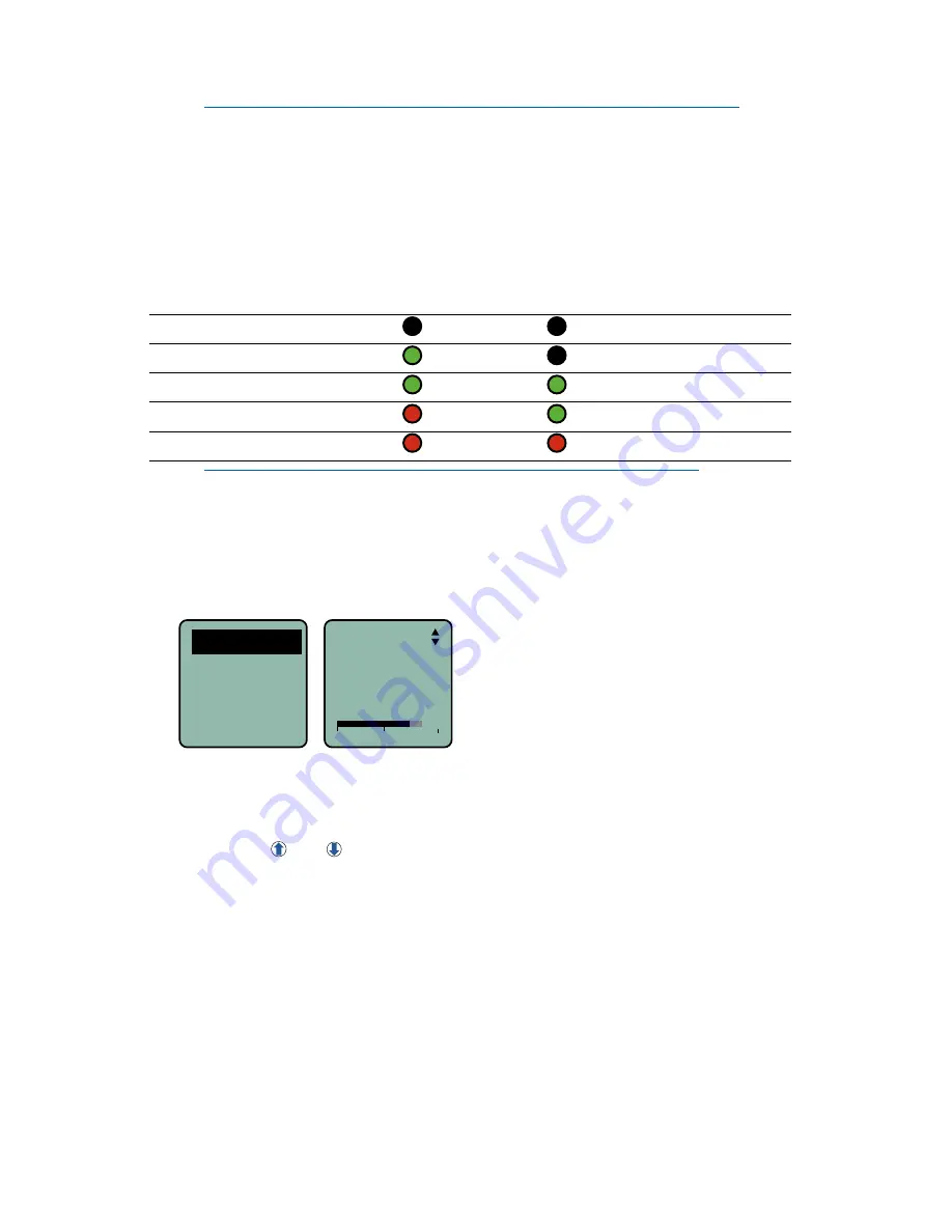
The two bicolor Modulation LEDs on the transmitter control panel provide a 

visual indication of the audio signal level entering the transmitter. The LEDs 

will glow either red or green to indicate modulation levels as shown in the 

following table. Full modulation is achieved at 0 dB, when the “-20” LED first 

turns red. The limiter can cleanly handle peaks up to 30 dB above this point.

Signal Level 

-20 LED 

-10 LED

Less than -20 dB 

 Off 

 Off

-20 dB to -10 dB  

 Green 

 Off

-10 dB to +0 dB 

 Green  

 Green

+0 dB to +10 dB 

 Red 

 Green

Greater than +10 dB 

 Red 

 Red

NOTE: It is best to go through the following procedure with the 

transmitter in the standby mode so that no audio will enter the sound 

system or recorder during adjustment.

1)  With fresh batteries in the transmitter and power the unit on in the standby 

mode (a brief press on the power switch with L-Series transmitters).

2)  Navigate to the Gain setup screen.   
 

Gain

Freq.
ProgSw
Compat

-40

-20

0

Gain

25

LMb menu shown

3)  Prepare the signal source. Position a microphone the way it will be used 

in actual operation and have the user speak or sing at the loudest level 

that will occur during use, or set the output level of the instrument or 

audio device to the maximum level that will be used.

4)  Use the   and   arrow buttons to adjust the gain until the –10 dB glows 

green and the 

–20 dB LED starts to flicker red during the loudest peaks 

in the audio.

5)  Once the transmitter input gain has been set, the signal can be sent to 

the sound system or recorder for level adjustments, monitor settings, etc. 

6)  Always leave the transmitter gain adjustment set according to these 

instructions, and do not change it to adjust the audio output level of the 

receiver.

Other Transmitters:

Earlier Lectrosonics transmitters provided LEDs to accurately indicate full 

modulation, with continuously variable gain controls for a precise adjustment. 

The LEDs operate in the same manner as those shown here for the L-Series 

transmitters.

Содержание L series

Страница 1: ...ssist with initial setup and operation of your Lectrosonics product For a detailed user manual down load the most current version at www lectrosonics com L Series Wireless Microphone System LR Receiver LMb Transmitter LT Transmitter Digital Hybrid Wireless Technology U S Patent 7 225 135 26 Mar 2015 ...

Страница 2: ...ICS INC 2 FCCID DBZLMBC1 Lectrosonics Inc Made in U S A IC 8024A LMBC1 614 4 691 1 MHz Model LMBC1 S N XXXXX IR 5 623 400 40 20 0 A IR PORT 20 10 BAT PWR FUNC 10 20 AUDIO 5 623 400 40 20 0 A Controls and Features ...

Страница 3: ... 15 of the FCC rules Operation is subject to the condition that this device does not cause harmful interference CAN RSS Gen CNR Gen CAN ICES 3 B NMB 3 B Model LR XX Made in the USA Serial No XXXXX Frequency block XXX XXX X XXX X MHz Battery Doors LT and LR models LMb model ...

Страница 4: ... remain MENU SEL Button Pressing this button enters the menu and selects menu items to enter the setup screens BACK Button Pressing this button returns to the previous menu or screen Power Button Turns the unit off and on and enters the power menu Arrow Buttons Used to navigate the menus Navigating the Menus Menu setup items are arranged in a vertical list on the LCD Press MENU SEL to enter the me...

Страница 5: ...se arrow keys to select step size 100 kHz 25 kHz Squelch Bypass Backlight Time Retore Factory default settings Tx Battery Select from listings Use arrow keys to select battery type Rx Battery Select from listings Use arrow keys to select battery type Compat Mode Select from listings Use arrow keys to select compatibility mode Use arrow keys to select audio output polarity Normal Inverted Polarity ...

Страница 6: ...he RX Battery setup screen 2 Select Frequency Step Size Navigate to Step Size in the LCD menu and select 100 kHz or 25 kHz as needed to match the associated transmitter 3 Select Receiver Compatibility Mode Navigate to Compat Mode on the menu and press MENU SEL to enter the setup screen The optional modes will appear one at a time Use the UP and DOWN arrow buttons to scroll through the list When th...

Страница 7: ... Mode 6 is a special compatibility mode for use with another brand of wireless Contact the factory for details IFB works with Lectrosonics models such legacy analog models bearing IFB in the model number or Digital Hybrid Wireless models that offer the IFB com patibility mode 4 Find a Clear Frequency with Smart TuneTM Optimum range will be realized if the system is set to a frequency where few or ...

Страница 8: ...s chosen by Smart Tune Then set this frequency on the transmitter 4a Find a Clear Frequency Manually A manual scan will create a graphical display on the LCD showing the pres ence and strength of RF signals entering the receiver Sections of the tuning range with clear frequencies that have little or no RF energy clear spectrum are easy to identify Navigate to RF Scan on the menu and press MENU SEL...

Страница 9: ...smitter to Matching Frequency and Compatibility Mode If you have not already set the frequency on the transmitter in the previous procedures use IR Sync or complete the settings manually Lectrosonics transmitters with IR Sync On the LR receiver navigate to IR Sync on the menu and press the MENU SEL button Hold the transmitter and receiver fairly close to each other within two feet or so and positi...

Страница 10: ...d power the unit on in the standby mode a brief press on the power switch with L Series transmitters 2 Navigate to the Gain setup screen Gain Freq ProgSw Compat 40 20 0 Gain 25 LMb menu shown 3 Prepare the signal source Position a microphone the way it will be used in actual operation and have the user speak or sing at the loudest level that will occur during use or set the output level of the ins...

Страница 11: ...ted device A built in tone generator makes matching the output level to the connected device easy and accurate 1 Navigate to Audio Level in the LR receiver menu and press MENU SEL to enter the setup screen Use the arrow keys to reduce the level to minimum 50 dBu 2 Turn on the 1k tone MENU SEL UP arrow in the Audio Level setup screen 3 On the connected device set the input to line level if availabl...

Страница 12: ...is warranty applies only to items returned to Lectrosonics Inc or an authorized dealer shipping costs prepaid within one year from the date of purchase This Limited Warranty is governed by the laws of the State of New Mexico It states the entire liablility of Lectrosonics Inc and the entire remedy of the purchaser for any breach of warranty as outlined above NEITHER LECTROSONICS INC NOR ANYONE INV...

Отзывы: