background image

Modular Digital Hybrid Wireless™ Receiver

Rio Rancho, NM

1

Stop Mode

To stop scanning (but not exit Scan), press the front 

panel Function button once.  In Stop mode, each verti-

cal band in the display still represents eight frequencies 

(800 kHz).  Rotating the MENU/SELECT control scrolls 

the cursor for the currently selected receiver across the 

tuning range.  As the cursor scrolls across the tuning 

range, the Transmitter Frequency Select Switch settings 

associated with the cursor location are shown in the up-

per right corner of the display.
Up to six individual cursors appear in Scan mode, 

depending on the number of receiver modules installed 

and the diversity modes selected.  (See DivMode Setup 

Screen.)   Pressing the Receiver Select button for an 

individual receiver selects the corresponding cursor for 

that receiver.  (The selected cursor blinks.)  The cor-

responding Receiver Module box will be highlighted, 

and that receiver will be monitored at the PHONES jack.  

Rotating the MENU/SELECT control moves the select-

ed cursor and tunes the selected receiver in real time.
The location of the selected cursor also controls the 

value displayed for the Transmitter Frequency Select 

Switch settings.  Changing the cursor location, or se-

lecting a different receiver module (and thus a different 

cursor) will change the value for the Transmitter Fre-

quency Select Switch setting.

Zoom Mode

Pressing the Function button from Stop mode accesses 

Zoom mode which displays an expanded portion of the 

spectrum around a fixed, vertical cursor.  In this view, 

each vertical band represents one frequency (100 kHz).  

As the MENU/SELECT control is rotated, a 6.6 MHz 

window moves across the frequency block.  The relative 

position of this window in the frequency block range is 

indicated on a horizontal bar at the bottom of the spec-

trum display.

Warning: If one of the receiver modules is 

manually tuned in Stop mode or Zoom mode, 

the new frequency setting will persist when 

exiting Scan.  Moving the cursor for the 

selected receiver module tunes that receiver in 

real time.

Pressing the Function button again returns to Scan 

mode and resumes the scanning function.

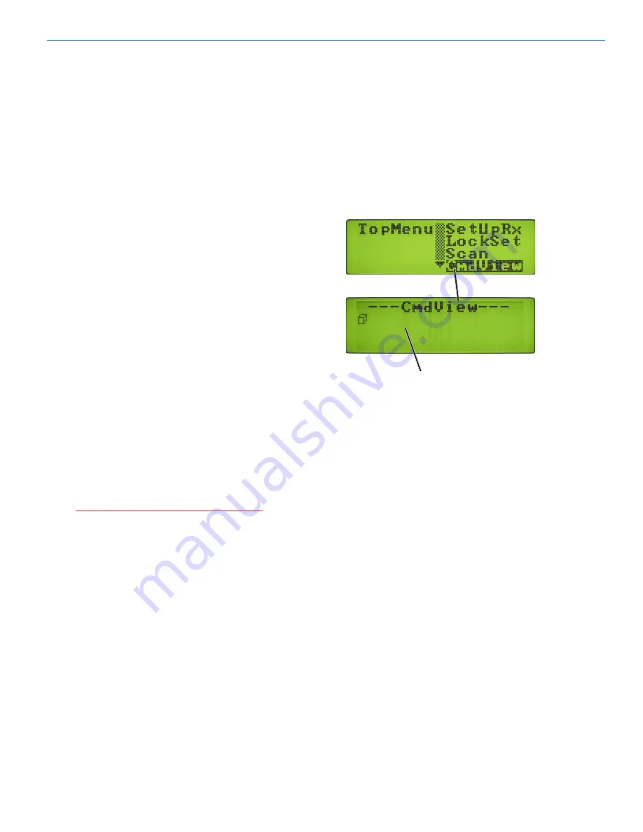
CmdView Screen

The CmdView Screen is used primarily for diagnostics 

and for troubleshooting communication problems when 

setting up serial remote control systems.
The CmdView screen is a convenient utility to assist 

in verifying correct serial commands have been sent 

to the unit.  This screen offers feedback when using 

computers or other devices connected to the RS-232 

or USB serial ports.  As commands are transferred 

through either of these ports to the VR Field System, 

those commands are listed in order of entry on the 

CmdView Screen.

Rolling.list.of.serial.commands.

will.be.displayed.here

Содержание VR Field

Страница 1: ...Digital Hybrid Wireless Portable Modular Receiver System Digital Hybrid Wireless U S Patent 7 225 135 REFERENCE MANUAL Rio Rancho NM USA www lectrosonics com Fill in for your records Serial Number Purchase Date ...

Страница 2: ...VR Field Receiver LECTROSONICS INC ...

Страница 3: ...fiers and SAW Filters 7 Digital Pulse Counting Detector 7 Power Supply 8 VRS Functional Block Diagram 8 VRT Functional Block Diagram 8 VR Field System Controls and Functions 9 Front Panel Controls and Functions 9 POWER Button 9 Function Button 9 LCD Screen 9 PUSH FOR MENU SELECT Rotary Control 9 LEVEL Control 9 PHONES Jack 9 Receiver Select Buttons 9 BACK Button 9 Rear Panel Features 10 Power Inpu...

Страница 4: ...rogrammable Frequency Group Entries 17 DivMode Setup Screen 18 SmartDiversity 18 OptiBlend 18 Frequency Diversity 19 LockSet Setup Screen 19 Scan Function 20 Scan Mode 20 Stop Mode 21 Zoom Mode 21 CmdView Screen 21 Frequency Coordination 22 Frequency Compatibility Chart 22 Frequency Compatibility Diagram 23 Using the Scan Function 24 Call Lectrosonics 24 Antenna Use and Placement 25 Phantom Power ...

Страница 5: ...al processor DSP A D and D A converters and audio output circuits plus mechani cal rack mounting for up to six receiver modules The system can be setup and operated either through front panel controls and display or via rear panel USB or RS232 ports connected to a Windows 2000 XP or Vista based computer system and VRpanel which is part of the LecNet2 software package See VR Field Installation Guid...

Страница 6: ...mp Note While all audio channels are sent to the respective Audio Output XLR jacks only one audio channel at a time may be monitored via the front panel PHONES jack See Headphone Mixer and Amp Compatibility Modes The VR Field System was designed to be compatible with Lectrosonics Digital Hybrid 400 Series transmit ters and will yield the best performance when operating in Digital Hybrid mode Howev...

Страница 7: ...g front end PLL and VCO Circuits Each receiver module is frequency agile and can be set to operate on any one of 256 frequencies within its tun ing range The PLL synthesizer receives instructions from the microprocessor then uses those instructions to set the receiver module s operating frequency by controlling the 1st and 2nd Voltage Controlled Oscilla tors VCO Switched Diversity Reception All in...

Страница 8: ... receiver has a built in Poly Fuse to protect the unit If a problem occurs that trips this fuse it will reset after the power supply is disconnected for about 15 seconds Note To use external power temporarily disconnect the power supply cable that connects the battery to the master unit VRS Functional Block Diagram VRT Functional Block Diagram For Internal Power the VR FIeld uses a single NP1 type...

Страница 9: ...or navigating and selecting Setup Menus or Setup Screens and for setting parameters within the Setup Screens VR Field System Controls and Functions LEVEL Control The LEVEL control is used to adjust the output level of the front panel PHONES jack PHONES Jack The stereo PHONES jack is provided for monitoring the audio output of selected receivers Only the audio from a single receiver or diversity pa...

Страница 10: ...RS 232 communication links Antenna Input Jacks Two BNC input connectors are provided for right angle whip antennas cables from remote antennas or cables from another VRM An internal mulitcoupler ensures the RF is applied equally to all installed Receiver Mod ules and also to the Antenna Output Jacks Antenna Output Jacks Two pairs of 50 Ohm BNC output jacks provide zero gain antenna loop throughs f...

Страница 11: ...w Screen which displays the operating sta tus of the installed receiver modules Overview Screen The Overview Screen which appears after the Powerup Sequence is completed is the normal display during operation This screen is sectioned into six equal col umns one for each receiver module location Any given column displays information about the corresponding receiver module This information includes ...

Страница 12: ...me The operating frequency of a receiver module can also be set through the Scan Function See Scan Function for more information Tuning Group Select Shortcut To instantly select or change a Tuning Group from the Receiver Detail Screen hold the FUNCTION button then press a Receiver Select button according to the chart below Receiver Info Screen From the Receiver Detail Screen pressing the front pan...

Страница 13: ...up Screen displays the selected receiver audio output level setting and reference tone status Top Menu The Top Menu is accessed from the Overview Screen by pushing the MENU SELECT rotary control Rotating this control navigates through the various menu items The four menu items are SetUpRx LockSet Scan CmdView Rotate the MENU SELECT control to highlight a menu item then push the control to access t...

Страница 14: ... the transmitters see 9V TIM and AA TIM Correctly set this feature will ensure that adequate warning will be provided in advance of battery failure Depending on the TxBatt mode a battery icon or timer will be displayed on both the Overview and Receiver Detail screens and the battery level or timer value will be displayed on the Receiver Infomation Screen The icon timer or voltage only appears afte...

Страница 15: ...played in both the Overview and Receiver Detail screens and the TxBatt Setup Screen for the selected receiver mod ule Its format is H MM and it can run for up to 10 hours 9 59 before rolling over The timer s colon blinks in both the Main Receiver screen and the Receiver Detail Screen when the timer is active and receiving RF from the associated transmit ter When the transmitter or VR is turned off...

Страница 16: ...e case that a receiver does not appear to be working properly or to determine the nature of RF interference However it should be used with caution The selected receiver can output very loud noises in this mode To enable pilot tone bypass mode for a Receiver Module navigate to the Pi lotBP Setup Screen and press the appro priate Receiver Select button Rotate the MENU SELECT con trol to select BYPAS...

Страница 17: ... mable frequency group the tuning behavior is modified slightly Turning the MENU SELECT control navigates among the frequencies that are in the currently selected tuning group Turning the MENU SELECT control while holding down the Function button allows any frequency to be selected whether or not it is in the currently selected turning group Any time the currently tuned frequency is not in the cur...

Страница 18: ...modules operate independently with each module having its own set of controls and indicators In ratio diversity and frequency diversity modes the paired receiver modules act as a set Pressing the Receiver Select button for one member of the pair has the effect of selecting or operating on both receiver modules in the pair Frequency diversity adds another facet in that it uses two transmitters requ...

Страница 19: ...one bypass and output level are all matched For example setting the compatibility mode to Digital Hybrid in one receiver of the pair auto matically sets the other receiver to the same compatibil ity mode However transmitter battery monitoring and operating frequency are set independently Frequency Diversity has two modes of operation nor mal mode and test mode Test mode is automatically activated ...

Страница 20: ...g function from the Over view Screen push the MENU SELECT control to enter the Top Menu then rotate the control to highlight Scan Pressing the MENU SELECT control again begins the scanning function Scan Mode The LCD switches to the Scan screen and automatically starts progressively scanning all installed frequency blocks The unit will scan continually accumulating the highest peak seen on each cha...

Страница 21: ...d thus a different cursor will change the value for the Transmitter Fre quency Select Switch setting Zoom Mode Pressing the Function button from Stop mode accesses Zoom mode which displays an expanded portion of the spectrum around a fixed vertical cursor In this view each vertical band represents one frequency 100 kHz As the MENU SELECT control is rotated a 6 6 MHz window moves across the frequen...

Страница 22: ...t was designed to as sist in minimizing intermodulation problems for multiple channel wireless systems It does this by identifying potential intermodulation problems and listing compat ible frequencies and frequency groups This chart can be used with all Digital Hybrid Wireless 400 Series receivers The chart divides the frequency blocks used in the North American market into Set 1 and Set 2 then f...

Страница 23: ...Modular Digital Hybrid Wireless Receiver Rio Rancho NM 23 Frequency Compatibility Diagram See guidelines on page 16 for explanation ...

Страница 24: ...e variety of sources including TV station signals other wireless equipment in use nearby or from intermodulation within the VR Field system itself The RF spectrum analyzer built into the VR Field system uses a receiver in each frequency block to scan the tunable spectrum and find clear chan nels with little or no interference After scanning and finding the needed number of clear channels one final...

Страница 25: ...d fills or leaves the room The VR Field System offers a several sophisticated diversity designs which can overcome most dropout problems In the event however that you do encounter a dropout problem first try moving the one of the re mote antennas at least three or four feet from its current location This may alleviate the dropout problem at that location If dropouts are still a problem try moving ...

Страница 26: ...nas that provide a useful directional pattern over a broad frequency bandwidth Ideal for portable applications including temporary setups for field production ARG15 ARG100 Coaxial cables for remote antennas are available from Lectrosonics in a variety of lengths from 2 to 100 ft Cables include Velcro tie wraps VRS Standard receiver module VRT Tracking receiver module P1196 Receiver Module Retainer...

Страница 27: ...lem changes channels If problem follows Receiver Module the module may be defective RF Problems All Modules No Antenna Icon in any Receiver Module on Overview Screen The antenna icon is only present in switched diversity and frequency diversity modes and never present in ratio diversity mode RF Level Weak Improper length antenna if using UHF Whip Antennas Excessive length of cable between VR Field...

Страница 28: ...d the audio will be muted squelched In the other compatibility modes no pilot tone is used and the P is never displayed Audio is present whenever the receiver detects a sufficiently strong signal Activating the pilot bypass function in any mode causes a lowercase b to appear in the pilot indicator position on the main window and forcibly unsquelches the audio Poor signal to noise ratio Associated ...

Страница 29: ...Interface Problems New Hardware Found message does not appear when USB cable plugged into VR Field System Defective USB cable between Computer System and VR Field or between Computer System and USB Hub Multiple System Configuration Defective USB Hub Multiple System Configuration VRpanel software installed but USB Driver not installed See Installing LecNet2 Software and USB Driver VRpanel detected ...

Страница 30: ...r 50 MHz 3 dB VRS Standard Module 30 MHz 3 dB VRT Tracking Module 11 MHz 3 dB Sensitivity 20 dB Sinad 0 9 uV AM Rejection 60 dB 2 uV to 1 Volt Image Spurious Rejection 85 dB Diversity Methods Switched ratio and frequency FM Detector Digital pulse counting detector 300 kHz Audio Performance overall system Frequency Response 32 Hz to 20 kHz 1dB overall system using a UM400 transmitter in Digital Hyb...

Страница 31: ...f warranty repairs Returning Units for Repair For timely service please follow the steps below A DO NOT return equipment to the factory for repair without first contacting us by email or by phone We need to know the nature of the problem the model number and the serial number of the equipment We also need a phone number where you can be reached 8 A M to 4 P M U S Mountain Standard Time B After rec...

Страница 32: ...rosonics Inc will pay for the cost of returning your equipment to you This warranty applies only to items returned to Lectrosonics Inc or an authorized dealer shipping costs prepaid within one year from the date of purchase This Limited Warranty is governed by the laws of the State of New Mexico It states the entire liablility of Lectrosonics Inc and the entire remedy of the purchaser for any brea...

Отзывы: