3. Installation
12
164201241-001 Rev. C0
5.
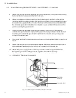
Attach the ground mounting brackets from the supplied kit to the ground skirt using
the 5/16-18 x 3/4” screws and the 5/16"-18 nuts.
6.
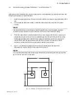
Make a template from sheet metal or wood indicating the position of the ground
mounting bracket mounting holes. Drill out the four holes in the template and insert
two customer-supplied 5/8" x 4" bolts. The head of the bolts will be embedded into
the concrete pad when installation is complete. Leave sufficient thread above the
pad for securing the ground skirt.
7.
Center and secure template (with bolts in position) over the form. Be sure the
conduit stub-ups for the AC input and the ground rod are positioned at the desired
locations just outside the ground skirt.
Optional: the conduit stub-ups may pass
through the cement pad.
8.
Pour, level, and finish the concrete to the bottom of the template. Allow to cure for 24
hours.
9.
Attach the ground skirt to power supply cabinet. Align skirt inside the bottom lip of
the cabinet and secure with the 10-32 x 3/8" screws from the parts kit.
10. Attach the power supply to the concrete pad with customer-supplied 5/8" nuts
through the ground mounting brackets. Tighten all hardware securely.
11. Continue to “Electrical Connections”
3.2
Ground Mounting
(Models PSF-MXG-*** and PCS-MXG-***), continued
Fig. 3-4 Attaching the MiniMax Cabinet to the Pad
Rear Cover
Mounting
Brackets
Concrete Pad


