background image

BeMe 

User Manual

Supporting 

Children

English

Содержание BeMe

Страница 1: ...BeMe User Manual Supporting Children English...

Страница 2: ...p 32 12 Annual Product Inspection p 33 13 Re issuing Leckey Products p 34 14 Product Servicing p 35 15 Technical Information p 36 16 How to Unpack and Assemble the Seating System p 42 17 Fitting the...

Страница 3: ...f 35 kg Medium Backrest is suitable for children with a maximum user weight of 50 kg Large Backrest is suitable for children with a maximum user weight of 70 kg Small High Low Chassis is suitable for...

Страница 4: ...50 3771 Sunrise Medical Q400 150 3771 Indications for Use BeMe is a modular seating system designed to cater for the needs of children with a variety of disabilities which effect their ability to sit...

Страница 5: ...e high low chassis and seat in extremes of its range of positions will reduce its stability When using high low chassis only use the seat at maximum height and or maximum seat recline when on level gr...

Страница 6: ...hions and encourage corrosion on the chassis Only use non abrasive household cleaners and moist cloths do not use running water on the upholstery whilst it is still attached to the seat See Section 10...

Страница 7: ...d products and components For goods provided by Sunrise Medical Pty Ltd in Australia our goods come with a guarantee by Sunrise that cannot be excluded under the Australian Consumer Law You are entitl...

Страница 8: ...justments for Daily Use SECTION 10 Cleaning and Care SECTION 11 Daily Product Inspection Leckey recommend that a written record is maintained of all those who have been trained in the correct use of t...

Страница 9: ...usted accidentally by other children 7 9 When the Leckey seating systems are used on the High Low chassis we do not recommend that users are moved over uneven surfaces when in the equipment All due ca...

Страница 10: ...If the Leckey BeMe seat is being used in a vehicle the following points must be adhered to The Leckey BeMe must be positioned forward facing It must be used with an Unwin Restraint System and a head s...

Страница 11: ...zure activity Children dependent on the use of percutaneous endoscopic gastrostomy Medical instability including compromised respiratory or cardiovascular function Dependant on 3rd party life sustaini...

Страница 12: ...ined in section 11 of this user manual Adjust the seat to a comfortable angle to facilitate transfer Lock all the castors ensuring that they are facing outwards to maximise product stability If the se...

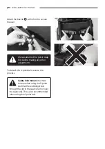
Страница 13: ...the flip away laterals pull the pin shown in the picture below SECTION 9 3 ATTACHING DETACHING AND ADJUSTING 4 POINT BELT To attach the 4 point belt pass the grey webbing through the upper slot in the...

Страница 14: ...e front to secure the user Always attached the pelvic strap first before making any other adjustments Safety Information You must ensure when using the 2 point belt that the webbing is fed through the...

Страница 15: ...the cam buckles Ensure belt is orientated with padding facing towards child To detach the 2 point belt reverse the process Attach the buckle at the front to secure the user Always attached the pelvic...

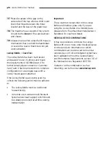
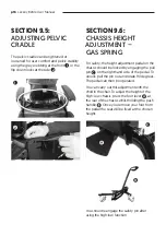
Страница 16: ...l on the chassis should be locked by engaging the pull pin on the right hand side of the pedal To unlock pull the pin out and rotate 90 degrees The pedal can then be operated You can carry out this ad...

Страница 17: ...ch pump To lower the chair place your foot under the pedal and gently lift the pedal up the chair will automatically lower SECTION 9 8 CHASSIS HEIGHT ADJUSTMENT ELECTRIC The powered chassis can be eas...

Страница 18: ...y for approximately one hour The electrical seat height adjustment can be operated whilst the battery is on charge Before operation ensure that the cable to the hand controller is not caught or wrappe...

Страница 19: ...SSIS Always keep the tilt in space lever in the locked position to prevent accidental actuation of the lever which could cause the seat unit to jolt and possibly cause injury to the child Please use t...

Страница 20: ...eat Before you adjust the tilt in space angle of the seat always ensure the pelvic belt is secured preventing the user from sliding forward in the seat SECTION 9 10 TILT IN SPACE MEDIUM HIGH LOW CHASS...

Страница 21: ...eventing the user from sliding forward in the seat SECTION 9 11 TILT IN SPACE LARGE HIGH LOW CHASSIS To adjust the tilt angle pull the lever on the push handles 1 tilt the seat to the required angle a...

Страница 22: ...f 250psi in the uncompressed shock system Exceeding the maxium air pressure of 250lbs inch could result in serious injury SECTION 9 12 ADJUSTING DYNAMIC BACKREST RESISTANCE The resistance to increasin...

Страница 23: ...air pressure the amount of use the sitting style and personal preferences The best way to adjust the return strength is to decrease it completely and test by placing the user in the seat Slowly increa...

Страница 24: ...JUSTMENT To adjust the butterfly harness either change the amount of webbing passing through the cam buckles at the back of the seat base or top of the backrest Or adjust the length of the webbing on...

Страница 25: ...ould be tightened securely Please be aware of the gap on the underside of the Tray where a child could insert their finger between the metal bracket and the base of the plastic tray To detach the tray...

Страница 26: ...ocate the cam lever in the centre of the armrest Raise the cam lever to unlock and change the angle of the armrest to the desired position Secure by lowering the cam lever to the locked position Alway...

Страница 27: ...e straps should be placed over the bridge of the foot and over the toes The front strap can be fed through one of two slots on either side of the sandals depending on the size of the user s feet To dr...

Страница 28: ...ADJUSTING ANKLE HUGGERS To adjust the ankle wrap adjust the position of the Velcro straps around the bridge of the foot and around the ankle To adjust the ankle hugger adjust the position of the Velc...

Страница 29: ...position To adjust the height of the push handle rotate to loosen both the locking levers on the push handle tubes and raise or lower to the desired position Rotate the locking levers to tighten into...

Страница 30: ...cure in place push down firmly on the lever Orientate the pommel so that it sits external to the seating area To attach the femoral guide slot the femoral guide stem into the receiver on the seat and...

Страница 31: ...uration after multiple washes at 60 C but this will not affect the performance of the fabric To prevent this a lower temperature can be used Please remove the foam from the following covers before was...

Страница 32: ...o not use solvents to clean plastic or metal components 4 Make sure the product is dry before use SECTION 11 DAILY PRODUCT INSPECTION Therapists Parents Carers We recommend that daily visual checks of...

Страница 33: ...chassis height adjustment mechanism is working properly If the chassis is foot pedal operated ensure the seat height doesn t change when the pedal is released Also check that the locking pin engages...

Страница 34: ...the use of an automated fogger disinfection system that is used to completely cover the product surfaces with a disinfectant agent The manufacturer s instructions for the chosen system should be refe...

Страница 35: ...rried out by technically competent persons who have been trained in the use of the product All international service enquiries should be directed to the appropriate Leckey distributor who will be deli...

Страница 36: ...dth Maximum Contoured mm 250 300 400 300 400 Femoral Width on Split Seat mm 90 125 110 160 90 125 110 160 Maximum Weight Limit kg 35 50 70 50 70 Backrest Small Medium Large Back Height mm 360 470 390...

Страница 37: ...ium Ind Hydraulic Medium Ind Out Large Hydraulic Large Power Footprint Width mm 535 690 690 740 800 800 Footprint Length mm 635 840 840 880 770 850 770 Tilt Range degrees 10 to 30 10 to 25 10 to 25 10...

Страница 38: ...1 8 15 7 11 8 15 7 Femoral Width on Split Seat inches 3 57 4 9 4 3 6 3 3 5 4 9 4 3 6 3 Maximum Weight Limit lbs 77 175 110 25 154 35 110 25 154 35 Backrest Small Medium Large Back Height inches 14 2 1...

Страница 39: ...edium Ind Out Large Hydraulic Large Power Footprint Width inches 21 1 27 2 27 2 29 1 31 5 31 5 Footprint Length inches 25 33 1 33 1 34 6 27 6 33 5 30 3 Tilt Range degrees 10 to 30 10 to 25 10 to 25 10...

Страница 40: ...with a damp cloth only Operation 5 deg C to 40 deg C 20 to 80 RH non condensing Transport and Storage 10 deg C to 50 deg C 20 to 80 RH non condensing Allow 2 hours for the device to come to room tempe...

Страница 41: ...Device Read The Instructions For Use Ce Mark Warning Manufacturer Serial Number Product Code Max Occupancy Weight Date Of Manufacture Latex Free Unique Device Identification Crash Tested Machine Wash...

Страница 42: ...attach the seat to the base you have purchased If you are fitting the seat to a mobility base please ensure you fit the interface plate to the mobility base first Instructions on how to attach the in...

Страница 43: ...e chassis you have purchased Before attaching the seat base ensure the locking latch at the front is released If the locking latch is locked then the following steps should be completed Locate the rig...

Страница 44: ...chassis interface G Rotate the front of the seat down H pressing down firmly until an audible click of the locking latches locking is heard Check that it is secure by pulling up on the front and rear...

Страница 45: ...ch need to be pressed in when inserting the lower stems Push the stems in until the poppers protrude from the other end of the receiving tubes Secure the handle in place by tightening the locking bolt...

Страница 46: ...e locking plate should be free to move along the bolt between the moulding and the nut Orientate the locking plate so that a short age faces forward The femoral bar assemblies come in a left and right...

Страница 47: ...he inside face and re tighten the clamp using the Allen key It may be required to adjust the position of the femoral bar to allow for the upper leg clamp to be inserted To do this loosen the bolt on t...

Страница 48: ...er slot in the receivers at the end of the femoral bars Slot the prongs into the left and right receivers ensuring the two holes on each side align It may be required to adjust the position of the fem...

Страница 49: ...ted on the underside of the contoured cushion assembly and the top surface of the seat plate Images required including velcro and alignment at front To attach the contoured seat to the seat base align...

Страница 50: ...g horizontally outwards on the paddles and then rotating upwards Place the base of the backrest into the receiver ensuring it is as deep into the receiver as it can go Rotate the paddles downwards and...

Страница 51: ...e end of the upper leg stem ensuring that the locking plate is retained within the upper leg stem extrusion Secure in place with the bolt using the Allen key The individual footrests can be attached i...

Страница 52: ...seat base and orientate the armrest with the adjustment cam levers facing outwards Place the armrest stem into the slot and push downwards Check that the armrest has self locked by pulling upwards on...

Страница 53: ...screws provided To remove or replace the attachment bolt reverse this process To detach the attachment bolts on sandals reverse the process To attach the sandal place it on the footplate so that the a...

Страница 54: ...d through the bottom and then top of the triglide Finally to lock the webbing in place pass it through the bottom of the triglide again Trim strap to required length To detach the ankle huggers revers...

Страница 55: ...h of the sandal and snap together Feed the triglide which is attached to the black and white webbing through the side slot of the sandal Feed the black and white Velcro webbing strip E through the opp...

Страница 56: ...t into the vertical slot from the front side of the backrest platework If the backrest cushions are in place they can be stretched out of the way Mesh the two side of the radial crocodile teeth circul...

Страница 57: ...lace the split washer then the plane washer onto the bolt and pass it through the hole in the radial clamp E engaging the threads of the t nut Secure in place with the Allen key To detach the lateral...

Страница 58: ...he lateral bracket Ensure the t nut nests between the two surfaces of the radial clamp Place the radial clamps into the recess at the front of the thoracic moulding ensuring the protrusion of the radi...

Страница 59: ...stic pad Position this assembly against the inside surface of the lateral bracket so that the bracket locates into the recess of the plastic pad and the machined part locates in the slot of the latera...

Страница 60: ...teral plastic moulding Position this assembly against the inside surface of the lateral bracket so that the bracket locates into the recess of the plastic moulding Place the split washer then the plan...

Страница 61: ...orresponding slot in the slim lateral plastic pad Position this assembly against the inside surface of the lateral bracket so that the bracket locates into the recess of the plastic pad and the machin...

Страница 62: ...nuts using the Allen key and a spanner To attach the hip guides to the basic backrest place the t nut into the hole at the front of the basic backrest platework ensuring the long edge of the t nut is...

Страница 63: ...into the recess in the front of the sacral moulding ensuring the short edges of the t nut are in line with the top and bottom surfaces of the recess If the backrest cushions are in place they can be m...

Страница 64: ...e the process This should only be done once before it is required to replace the basic backrest clamps also SECTION 16 22 ATTACHING AND DETACHING SMALL BASIC BACKREST SPACER To attach the small basic...

Страница 65: ...the top bar of the backrest and centralise Clamp together by accessing the head of the bolt through the hole on the outside surface of the extrusion and placing the end of the bolt through the hole in...

Страница 66: ...from the other side of the clamp Place the clamp over the top bar of the backrest and centralise Clamp together by placing the end of the bolt through the hole in the other half of the clamp engaging...

Страница 67: ...ACHING AND DETACHING UNIVERSAL HEADREST BRACKET To attach the universal headrest place the sleeve into the receiving bracket Slide the stem into the sleeve and secure using the hand lever E To detach...

Страница 68: ...acket Secure using the hand lever SECTION 16 27 ATTACHING AND DETACHING TRAY Before inserting the tray ensure that the cam lever located at the front of each armrest is open To attach the tray insert...

Страница 69: ...e process Please be aware of the gap on the underside of the Tray where a child could insert their finger between the metal bracket and the base of the plastic tray SECTION 16 28 ATTACHING AND DETACHI...

Страница 70: ...AIN CANOPY To attach the rain canopy the rain canopy backrest tube needs to be installed To remove the existing backrest tube loosen the bolts of the backrest height adjustment clamp and raise the tub...

Страница 71: ...secure the bolts Place the ends of the backrest tube into the receivers of the backrest height clamp Press in the poppers E at the sides and push the backrest tube down further Tighten the bolts of th...

Страница 72: ...AY COVER To attach the padded tray cover first remove the tray from the seat Undo the Velcro straps and slot the padded cover over the plastic tray To secure overlap the Velcro straps on the underside...

Страница 73: ...at Remove the two washers and bolts Position the elbow blocker bracket so that the edge of the pad rests on the top surface of the tray and align the holes Reattach the two bolts and washers and secur...

Страница 74: ...the cam buckle at the front Pull the webbing taught and secure the cam buckles Ensure belt is orientated with padding facing towards child Always attached the pelvic strap first before making any oth...

Страница 75: ...Ensure belt is orientated with padding facing towards child SECTION 16 33 ATTACHING AND DETACHING 2 POINT BELT Attach the buckle at the front to secure the user Always attached the pelvic strap first...

Страница 76: ...les Pass the grey webbing though the cam buckles at either side of the back of the seat E and secure the cam buckles E To attach the pelvic cradle to a basic backrest trim the rear Velcro strap to the...

Страница 77: ...CTION 16 35 ATTACHING AND DETACHING DYNAMIC BACK Use caution when assembling and fitting the dynamic backrest as there is a minor risk of finger nipping Align the holes of the aluminium bracket of the...

Страница 78: ...emove the shoulder blank moulding and replace with the shoulder wing upgrade ensuring that it is orientated in such a way that the head of the bolt is pointed upwards Secure in place with the 3 screws...

Страница 79: ...r onto the front surface of the clamp moulding SECTION 16 37 ATTACHING AND DETACHING SHOULDER ANGLE SPACER MODERATE BACKREST ONLY Secure the angled shoulder spacer using the four longer screws Reattac...

Страница 80: ...e seat To secure in place push down firmly on the cam lock Orientate the pommel so that it sits external to the seating area SECTION 16 38 ATTACHING AND DETACHING POMMEL If the attachment mechanism be...

Страница 81: ...receiver on the seat and press downwards Check that the femoral guide has self locked by pulling upwards on the femoral guide SECTION 16 39 ATTACHING AND DETACHING FEMORAL GUIDES To detach the femoral...

Страница 82: ...k paddles at the back of the seat base by pulling horizontally outwards on the paddles and then rotating upwards Place the base of the backrest into the receiver ensuring it is as deep into the receiv...

Страница 83: ...est Cushion s a Basic Backrest Foam then Cover b Moderate or Complex Backrest 3 Piece sacral then thoracic then shoulder 4 Pelvic Belt Cradle 2 point or 4 Point 5 Hip Pads 6 Chest Harness 7 Lateral Co...

Страница 84: ...tach the front of the basic seat cushion align the front of the cushion with the front of the seat ramps and press down to Velcro in place Locate the snap fasteners at the front of the seat base Drop...

Страница 85: ...secure in place with the fasteners Always check the seat base cushion is secure before placing the child in the seat To attach the front of the split seat cushion align the front of each side of the c...

Страница 86: ...lace Stretch the foam so that the back edge of the foam and the back edge of the seat base are aligned and press down to Velcro in place Ensure the slots in the foam run from side to side Slide the fr...

Страница 87: ...t the top and bottom of the foam Place the washer on the screw and pass the screw through the holes in the foam and the corresponding holes in the platework Using a spanner secure all four screws in p...

Страница 88: ...d secure in place with the snap fasteners There are openings at either side of the cover for harness connections Tuck the stretch fabric in between the foam and the platework along both sides of the b...

Страница 89: ...er with the moulding and secure in place with the snap fasteners at the sides and underneath the moulding To attach the thoracic cover slot the top of the sacral cover into the cavity on the underside...

Страница 90: ...into the cavity on the underside of the shoulder cover Align the shoulder cover with the moulding and wrap the cover over both ends securing in place with the zips Ensure the cut outs at the back of t...

Страница 91: ...he harness so the child cannot slide or creep forward in the seat To detach the pelvic cradle reverse the process E SECTION 17 10 ATTACHING AND DETACHING PELVIC CRADLE Place cradle on the seat base cu...

Страница 92: ...ver the moulding with the zip facing outwards Secure in place with the zip The internal label will help you identify right and left To attach the butterfly harness first locate the cam buckles at the...

Страница 93: ...de the cover over the plastic pad with the Velcro facing downwards Secure in place with the Velcro The bottom connection points are on the back of the seat base Pass the webbing through the cam buckle...

Страница 94: ...e plastic moulding with the Velcro facing downwards and the eyelet upwards Secure in place with the Velcro To attach the flexible lateral covers undo the Velcro and slide the cover over the plastic pa...

Страница 95: ...over so that the zip is closest to the bottom edge To attach the footrest cover first remove any hardware or straps that are attached to the footrest Place the footrest cover onto the top surface of t...

Страница 96: ...MMEL COVER To attach the pommel cover undo the Velcro and slide the cover over the plastic pad with the Velcro facing downwards and with the pad orientated to match the contours of the pad Secure in p...

Страница 97: ...undo the Velcro and slide the cover over the platework with the Velcro facing upwards and the pad orientated so that the solid grey fabric side faces towards the front of the seat Secure in place wit...

Страница 98: ...o the Velcro and wrap the cover over the platework with the Velcro facing downwards and the pad orientated so that the extension tab points towards the lateral pad and facing outwards Secure in place...

Страница 99: ...e use of the product Leckey recommend a written record is maintained of all clinical setups for this product Set the backrest height seat depth and footplate height before placing the child in the sea...

Страница 100: ...t base and move each seat leg component separately to a suitable position The seat leg components can be moved forward backwards and to 15 degrees abduction adduction Tighten both bolts to secure in p...

Страница 101: ...seat adjust to the desired position and tighten the bolts to secure in place Reset the front base foam piece F so that it rests up against the front inside surface of the platework Set the front conto...

Страница 102: ...t hip pads can be repositioned on the Velcro base where the short dashed lines aid positioning and alignment Align the back edge of the pads with the back edge of the platework To adjust the hip pad w...

Страница 103: ...adjust inward or outward to the desired position Tighten the bolt to secure in place To adjust the hip pad height remove the two bolts and reset into the adjacent hole combinations Ensure to move the...

Страница 104: ...s in the snap fastener at the side of the tube and push downwards Tighten the bolts of the backrest height adjustment clamp to secure in position The moderate and complex backrest pads have two clamp...

Страница 105: ...ing the backrest section forwards or backwards to the desired position Tighten the bolts to secure in position The complex clamps are found on the sacral thoracic and shoulder sections of the complex...

Страница 106: ...the backrest section forwards or backwards to the desired position Tighten the bolts to secure in position The complex clamps are found on the sacral thoracic and shoulder sections of the complex back...

Страница 107: ...krest section forwards or backwards to the desired position Tighten the bolts to secure in position The complex clamps are found on the sacral thoracic and shoulder sections of the complex backrest an...

Страница 108: ...ove Loosen the bolt and move the shoulder wing to the desired position Tighten the bolt to secure in position and zip up the cover To adjust the footrest height loosen the bolt and lengthen or shorten...

Страница 109: ...angle can be adjusted independently For the one piece footrest the bolts need to loosen simultaneously to allow for adjustment To adjust the angle of the footrest to accommodate dorsiflexion and plan...

Страница 110: ...trap around the ankle and the length of the strap through the triglide To position the user s feet in the sandals secure the Velcro straps provided so the foot is held in place The straps should be pl...

Страница 111: ...ES To adjust the ankle wrap adjust the position of the Velcro straps around the bridge of the foot and around the ankle To adjust the booties adjust the position of the Velcro strap around the bridge...

Страница 112: ...ck of the basic backrest or at the back of the moderate and complex backrest Adjust the height width and angle to the desired position and tighten to secure in place To adjust the lateral depth open t...

Страница 113: ...ateral strap The armrest can be adjusted into several incremental height positions To adjust the armrest height loosen the bolt which rests off centre from the midline of the plate With the end of the...

Страница 114: ...centre of the armrest Raise the cam lever to unlock and change the angle of the armrest to the desired position Secure by lowering the cam lever to the locked position To adjust the armrest depth remo...

Страница 115: ...he amount of webbing passing through the cam buckles at the back of the seat base or top of the backrest or adjust the length of the webbing on the harness straps in any of the four corners of the har...

Страница 116: ...tray angle locate the cam lever in the centre of the armrest Raise the cam lever to unlock and change the angle of the armrest tray to the desired position Secure by lowering the cam lever to the lock...

Страница 117: ...slide the pad along the slots into the desired position Tighten the bolts to secure in place To attach the 4 point belt pass the grey webbing through the upper slot in the seat moulding and then thro...

Страница 118: ...through the upper slot in the seat moulding and then through the cam buckle Pull the webbing taught and secure the cam buckles Ensure belt is orientated with padding facing towards child Attach the b...

Страница 119: ...at the side of the seat base or back of the seat Or adjust the length of the webbing on the front straps on either side To detach the 2 point belt reverse the process Safety Information You must ensur...

Страница 120: ...sets of femoral guides Loosen the bolts and move to the desired position Tighten to secure in place The backrest angle can be adjusted in two ways through the backrest recline mechanism and through t...

Страница 121: ...ate through 180 degrees Slot the vertical tubes back into the interface extrusion and end caps and insert the bolt through all Tighten the bolt with the nut to secure in place There are six positions...

Страница 122: ...eckey BeMe User Manual Backrest Recline Mechanism Backrest Interface symbol facing forward Seat to Back Angle Recline Range 90 0 25 90 10 15 The follow back angles can be achieved by the below combina...

Страница 123: ...an air pump supplied with every dynamic back on the main air valve of the dynamic mechanism To increase the air pressure pump air into the valve to the desired pressure To decrease the pressure press...

Страница 124: ...p124 Leckey BeMe User Manual Dynamic Back Strength Log Date Client Reference Strength PSI...

Страница 125: ...Leckey BeMe User Manual p125...

Страница 126: ...p126 Leckey BeMe User Manual...

Страница 127: ...Leckey BeMe User Manual p127...

Страница 128: ...adian Distributor Sunrise Medical 237 Romina Drive Unit 3 Concord ON L4K 4V3 sunrisemedical ca T 1 800 263 3390 F 1 800 561 5834 E mkt canada sunmed com James Leckey Design Limited 19 Ballinderry Road...

Отзывы: