background image

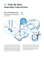
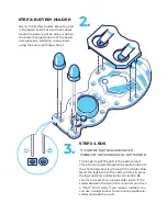
Place the red wire through hole marked with 
a square gold pad. Place the blue/black wire 
through the circle hole. Red indicates positive 
and the other wire is negative.Give yourself a 
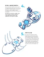
length of solder, 4 to 6 inches. Then, holding 
the solder in one hand and your soldering iron 
in the other, use the tip of your iron to heat up 

both the exposed wire of the vibration motor 
and the gold ring around the hole. Slowly feed 
in your solder into this joint until you've made 
a solid connection. Viola! One solder joint 
complete! Use the sticky back of the vibration 
motor to stick it to the board.

04.

 Step-By-Step

Assembly Instructions

1.

STEP 1: VIBRATION MOTOR

IT IS IMPORT THAT VIBRATION MOTOR IS 
PLACED CORRECTLY OR YOUR BUG WILL 
NOT TURN ON.  

Blue/Black

Wire

Red Wire

Vibration motor’s

 sticky back

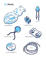
Содержание Jitterbug

Страница 1: ......

Страница 2: ...LEDs x2 On Off Switch x1 Jitterbug PCB x1 Battery Holder x1 Wire x1 Vibration Motor x1 3V Coin Cell Battery x1 01 Parts ...

Страница 3: ...FINE SOLDER WIRE Soldering Iron Solder Sucker Solder Safety Glasses Flush Cutters Snips Helping Hands 110 V 60 W Soldering Iron 02 Tools OPTIONAL RECOMENDED SOLDER SUCKER SS 4000 ...

Страница 4: ...eally quickly so you don t want your finger to be too close to the end Touch the solder to the solder pad It should liquify almost instantly and flow into the joint Move the solder around a bit to cover the entire solder pad You don t need very much to create a clean solder joint It should only take a few seconds Pull the solder away first and then the soldering iron Viola You have just created your ...

Страница 5: ...the tip of your iron to heat up both the exposed wire of the vibration motor and the gold ring around the hole Slowly feed in your solder into this joint until you ve made a solid connection Viola One solder joint complete Use the sticky back of the vibration motor to stick it to the board 04 Step By Step Assembly Instructions 1 STEP 1 VIBRATION MOTOR IT IS IMPORT THAT VIBRATION MOTOR IS PLACED CO...

Страница 6: ...e lead Place the long leds through the square hole and the short negative leg through the circular hole Bend the legs back so the LEDs will stay in place during soldering Solder each connection Be careful to create four unique solder joints If the solder between the two joints connects you have a short Don t worry if you make a mistake You can use a solder sucker to remove the additional solder an...

Страница 7: ...roll the length of wire and cut it into three parts Thread each one through the top under the bottom and back out the top It takes a little wiggling to get it into place Once you have the wire placed solder each connection Then cut the legs to your desired length Make sure all legs make contact with the table surface when flipped over STEP 5 LEGS BE CAREFUL COVER THE BOARD WITH YOUR HAND SO THE BIT...

Страница 8: ... rocketdept com QUESTIONS COMMENTS 6 Turn it on Slide the battery into place with the positive side up Flip the switch and watch it skitter around Try different surfaces The bug will be the most active on flat hard surfaces STEP 4 ENJOY ...

Отзывы: