Hardware Installation Manual of the IES Series
3
HWMN-IES-R20121030
·
It is recommended to mount the integrated in a space allowing air flow for good heat conduction. Use forced
cooling method to cool the system if necessary.
2. Connectors and Pin Assignment
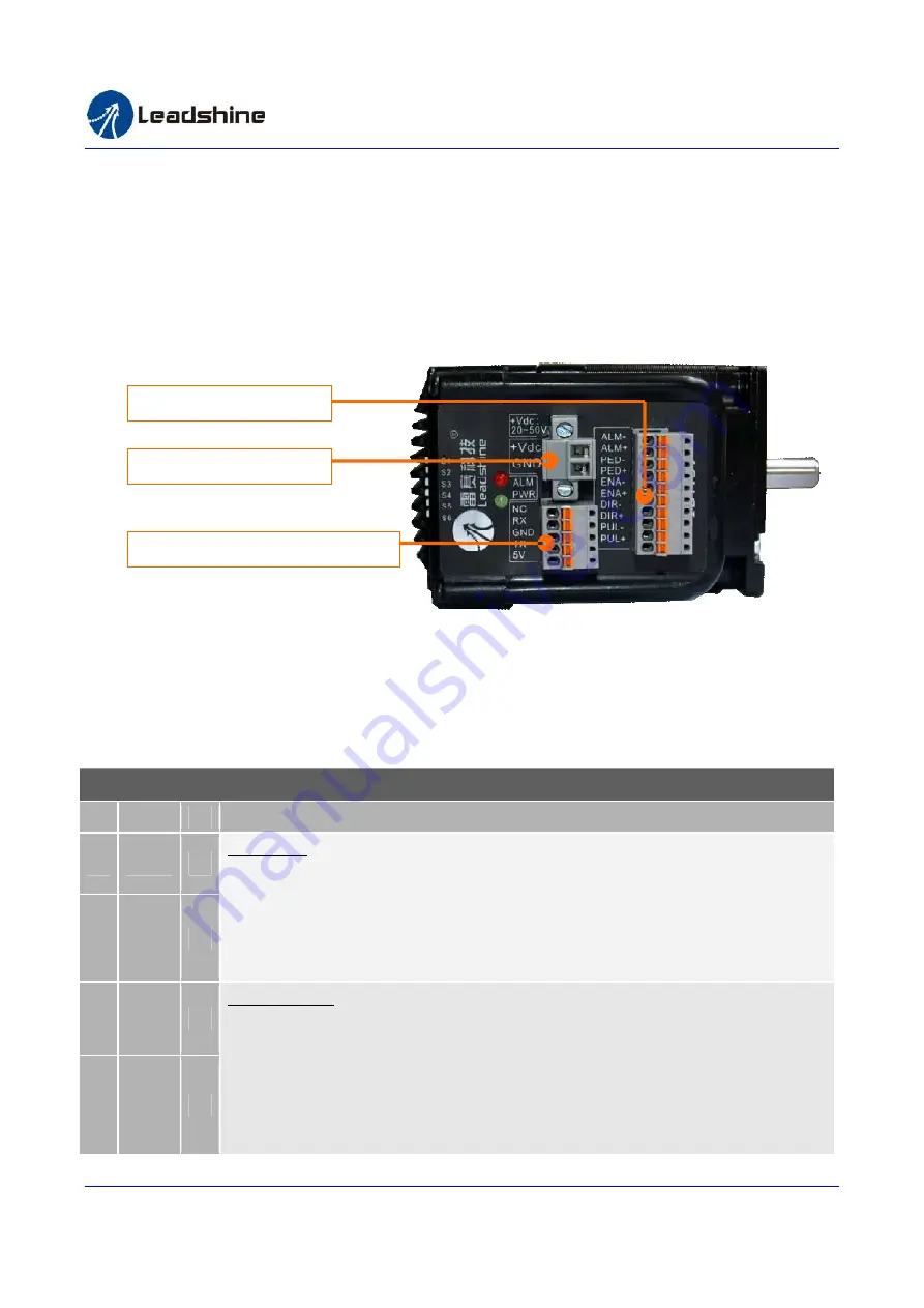
The IES23 has three connectors, a connector for control signals connections, a connector for RS232 communication
connections and a connector for power connections.
The control signal inputs include PULSE, DIRECTION and ENABLE and the control signal outputs include PED
(In-position) and ALARM. All the above control signals are integrated into one connector.
Control Signal Connector
Pin Name I/O
Description
1
PUL+
I
Pulse Signal: In single pulse (pulse/direction) mode, this input represents pulse signal, active
each rising or falling edge (Set by DIP switch S6); In double pulse mode (software
configurable), this input represents clockwise (CW) pulse, active both at high level and low
level. 4.5-24V when PUL-HIGH, 0-0.5V when PUL-LOW. For reliable response, pulse width
should be longer than 2.5
μ
s for 200K MAX input frequency or 1
μ
s for 500K MAX input
frequency.
2
PUL-
I
3
DIR+
I
Direction Signal: In single-pulse mode, this signal has low/high voltage levels, representing
two directions of motor rotation. In double-pulse mode (software configurable), this signal is
counter-clock (CCW) pulse, active both at high level and low level. For reliable motion
response, DIR signal should be ahead of PUL signal by 5
μ
s at least. 4.5-24V when DIR-HIGH,
0-0.5V when DIR-LOW. The motor direction can also be changed by DIP switch S5. Please
note that rotation direction is also related to motor-driver wiring match. Exchanging the
connection of two wires for a coil to the driver will reverse motion direction.
4
DIR-
I
Power Input Connector
RS232 Communication Connector
Control Signal Connector


