


A
A
C
C
S
S
3
3
0
0
6
6
D
D
i
i
g
g
i
i
t
t
a
a
l
l
A
A
C
C
S
S
e
e
r
r
v
v
o
o
d
d
r
r
i
i
v
v
e
e
M
M
a
a
n
n
u
u
a
a
l
l
R
R
e
e
v
v
1
1
.
.
0
0
RS232 Communication Connector
Pin
Signal
Description
I/O
1
NC
Not connected
-
2
+5V
+5V power only for STU.
O
3
TxD
RS232 transmit.
O
4
GND
Ground.
GND
5
RxD
RS232 receive.
I
6
NC
Not connected
-
High Voltage Connector
Pin
Signal
Description
I/O
1
U
Motor phase U
O
2
V
Motor phase V
O
3
W
Motor phase W
O
4
+Vdc
DC power Input (20-30VDC)
I
5
GND
Power Ground.
GND
More about I/O Signals
Signal
Description
PUL+/PUL-
Pulse input signal. In single pulse (pulse/direction) mode, this input represents
pulse signal, each rising or falling edge active (software configurable); 4-5V when
PUL-HIGH, 0-0.5V when PUL-LOW. In double pulse mode (pulse/pulse) , this
input represents clockwise (CW) pulse
,
active at both high level and low level . For
reliable response, pulse width should be longer than 0.85
μ
s. Series connect
resistors for current-limiting when +12V or +24V used. The same as DIR and ENA
signals.
DIR+/DIR-
Directions input signal. In single-pulse mode, this signal has low/high voltage
levels, representing two directions of motor rotation; in double-pulse mode
(software configurable), this signal is counter-clock (CCW) pulse
,
active at both
high level and low level. For reliable motion response, DIR signal should be ahead
of PUL signal by 5
μ
s at least. 4-5V when DIR-HIGH, 0-0.5V when DIR-LOW.
ENA+/ENA-
Enable input signal. This signal used for enabling/disabling the drive. High level
for enabling the drive and low level for disabling the drive. Usually left
UNCONNECTED
(ENABLED).
A
A
C
C
S
S
3
3
0
0
6
6
D
D
i
i
g
g
i
i
t
t
a
a
l
l
A
A
C
C
S
S
e
e
r
r
v
v
o
o
d
d
r
r
i
i
v
v
e
e
M
M
a
a
n
n
u
u
a
a
l
l
R
R
e
e
v
v
1
1
.
.
0
0
More about I/O Signals (Continue
’
)
Signal
Description
ALM+/ALM-
Alarm (Fault) signal output. OC output, high impedance when the working status is
normal and low impedance when over-voltage, over-current, phase error, encoder
error, limit error, position following error happens.
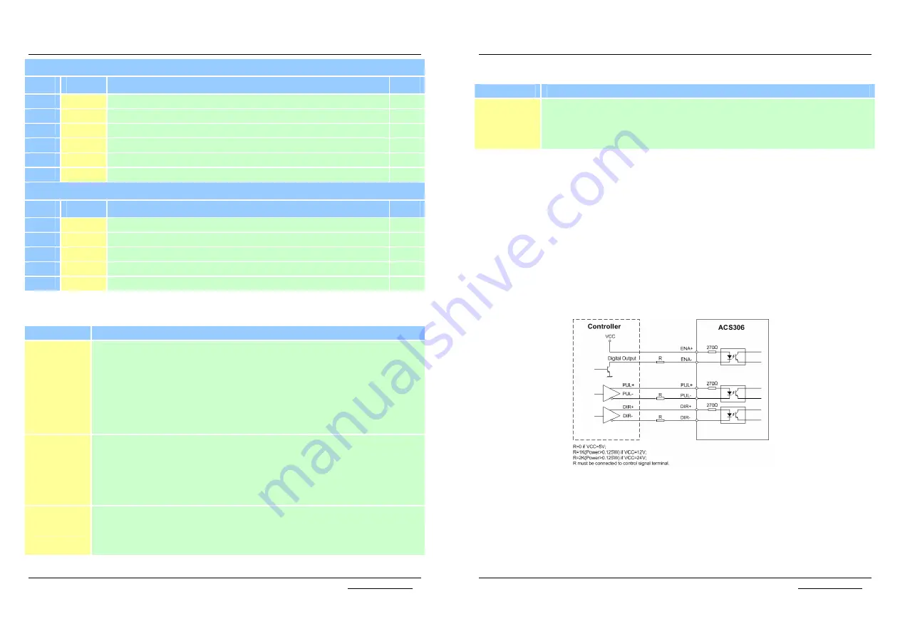
Control Signal Connections
The ACS306 has 3 differential logic inputs to accept Enable, Pulse and Direction
control signals and 1 OC (open collector) output for alarm (fault) output. These
inputs are isolated to minimize or eliminate electrical noises coupled onto the
control signals. Recommend use twisted wires and shielding cable for control
signals to increase noise immunity in interference environments. Keep these wires
far away from the power lines. In figure 3-2, input circuit for these control signals
and connections to a typical motion controller is illustrated. Figure 3-3 illustrates
connections to the controller with common-anode outputs.
Figure 3-1: Connections to controller with differential outputs
Содержание ACS306
Страница 13: ......


