background image


LT 4600A 

MULTIFORMAT VIDEO GENERATOR 


INSTRUCTION MANUAL (MAIN) 


Содержание LT 4600A

Страница 1: ...LT 4600A MULTIFORMAT VIDEO GENERATOR INSTRUCTION MANUAL MAIN...

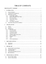
Страница 2: ...4 2 2 Features 4 2 3 Specifications 6 2 3 1 SDI Video Output 6 2 3 2 Genlock Function 13 2 3 3 Analog Black Output 13 2 3 4 Word Clock Output 14 2 3 5 AES EBU Digital Audio Output 14 2 3 6 External I...

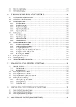
Страница 3: ...Trap Transmission 29 6 5 4 Setting the Trap Transmission Destination 30 6 5 5 Setting the Community Names 30 6 5 6 Retrieving the MIB File 31 6 6 Setting the Date and Time 32 6 7 Initializing Setting...

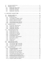
Страница 4: ...by Links 55 10 4 2 Settings Shared by Groups 55 10 4 3 Settings Shared by Channels 55 10 4 4 Turning the Audio On and Off 56 10 4 5 Selecting the Resolution 56 10 4 6 Selecting the Pre emphasis Mode 5...

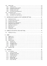
Страница 5: ...is Mode 68 11 5 Settings Shared by Channels 68 11 6 Selecting the Frequency 68 11 7 Setting the Level 68 11 8 Setting Clicks 69 11 9 Configuring Lip Sync 69 12 WORD CLOCK OUTPUT WCLK SETTING 70 12 1 A...

Страница 6: ...89 14 2 1 STATUS MENU 89 14 2 2 UTILITY MENU 90 14 2 3 REFERENCE MENU 92 14 2 4 SYSTEM MENU 93 14 2 5 BLACK MENU 94 14 2 6 SDI MENU 95 14 2 7 AES EBU MENU 100 14 2 8 WCLK MENU 101 14 3 Firmware Updat...

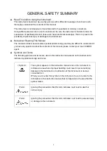
Страница 7: ...tand If you have any questions about the contents of this manual please contact your local LEADER agent Symbols and Terms The following symbols and terms are used in this instruction manual and on the...

Страница 8: ...he instrument has condensation within it wait for approximately 30 minutes before turning on the power Operating Humidity Range Use this instrument in an environment whose relative humidity is 85 RH o...

Страница 9: ...erminal to protect the user and the instrument from electric shock Ensure that the product is properly grounded for safe operation Warnings Concerning the Panel Sections of the panel are made out of g...

Страница 10: ...h with mild detergent and wipe gently While cleaning make sure that foreign materials such as water and detergent do not enter the product If liquid or a metal object enters into the instrument fire o...

Страница 11: ...nder the strictest quality control guidelines LEADER shall not be obligated to furnish the following free services during the warranty period 1 Repair of malfunction or damages resulting from fire nat...

Страница 12: ...ument contains sensitive components so it may be damaged if it is dropped or otherwise exposed to a strong shock 1 3 4 Electrostatic Damage Electronic components can be damaged by static discharge 1 3...

Страница 13: ...level A 3G B 3G SDI Level B 3G Collective term for 3G A and 3G B Logo App Logo App is a software for converting bitmap data bmp into 4 level monochrome data lg that can be used on the LT 4600A It is i...

Страница 14: ...40 line in size QVGA size can be overlaid at any position on the display Logo marks are 4 level monochrome data converted from bitmap data Safety Area Markers 90 and 80 safety area markers can be over...

Страница 15: ...ported Word Clock Output Equipped with one 48 kHz word clock signal synchronized with video signals AES EBU Serial Digital Audio Output Equipped with two 48 kHz AES EBU signals synchronized with video...

Страница 16: ...2 970GHz Outputs Two signals two outputs 1 Output Connector BNC 1 One signal two outputs for 3G B One signal one output for HD DL The output settings can be specified separately for the two signals bu...

Страница 17: ...94 50 30 29 97 25 24 23 98 P SMPTE ST 296 SMPTE ST 425 1920 1080 60 59 94 50 I SMPTE ST 274 SMPTE ST 425 30 29 97 25 24 23 98 P 30 29 97 25 24 23 98 PsF 12 bits 1920 1080 60 59 94 50 I 30 29 97 25 24...

Страница 18: ...4 50 I 30 29 97 25 24 23 98 P 30 29 97 25 24 23 98 PsF RGB 4 4 4 10 bits 1920 1080 60 59 94 50 I 30 29 97 25 24 23 98 P 30 29 97 25 24 23 98 PsF 12 bits 1920 1080 60 59 94 50 I 30 29 97 25 24 23 98 P...

Страница 19: ...white 100 black 0 625i 50 100 color bar EBU color bar BBC color bar check field blue field 100 green field 100 red field 100 flat field white 100 black 0 Automatic Switching Automatically switches be...

Страница 20: ...2 SPECIFICATIONS 10 can be turned on and off separately SD Action safe area 90 Title safe area 80 can be turned on and off separately Not available when the check field pattern is selected...

Страница 21: ...he blinking display and scrolling can be used simultaneously Logo Mark Logo Mark Data 4 level monochrome data from level 0 to 3 Maximum Size 320 dots 240 lines QVGA size Number of Logo Marks That Can...

Страница 22: ...ls 4 groups 3G B 32 channels link A link B 4 channels each 4 groups Sampling Frequency 48 kHz sampling synced with the video signal Resolution 20 bits 24 bits Pre emphasis OFF 50 15 CCITT only the CS...

Страница 23: ...T 1700 HD Tri Level Sync Signal SMPTE ST 240 SMPTE ST 274 SMPTE ST 296 Output Signal Outputs 6 3 signals 2 outputs Output Format Setting Each of the three signals can be configured independently Outpu...

Страница 24: ...emphasis OFF 50 15 CCITT only the CS bit is switched Frequency SILENCE 400 Hz 800 Hz 1 kHz Level 60 to 0 dBFS 1 dBFS steps Audio Click OFF 1 to 4 sec Lip Sync ENABLE DISABLE Sampling Clock Accuracy Gr...

Страница 25: ...D Number of Characters 20 characters 2 lines Backlight On Off 2 3 9 General Specifications Environmental Conditions Operating Temperature 0 to 40 C Operating Humidity Range 85 RH or less no condensati...

Страница 26: ...See section 4 3 Alarm Indications 5 CANCEL Cancels settings See section 4 5 Menu Operations 6 Arrow keys Used to move the cursor and to set values 7 ENTER Confirms settings See section 4 5 Menu Operat...

Страница 27: ...connector See chapter 11 AES EBU DIGITAL AUDIO OUTPUT AES EBU SETTING 4 WCLK OUT 48 kHz word clock output connector See chapter 12 WORD CLOCK OUTPUT WCLK SETTING 5 Ground terminal Connect the instrum...

Страница 28: ...llow the procedure below Attaching the Cover Inlet Stopper 1 Cover the power cord with the cover inlet stopper 2 Push the cover inlet stopper until you hear a click to attach it to the AC inlet 3 Chec...

Страница 29: ...4600A starts to initialize During initialization signals are not output and you cannot use the keys Startup Complete When the following screen appears the startup is complete Power on Settings See sec...

Страница 30: ...the USB memory device the following message appears 4 5 Menu Operations There are eight main types of menus that appear on the LCD The menu switches each time you press the MENU key when the menu leve...

Страница 31: ...played such as in IP ADDRESS use the and keys to move the cursor and the and keys to change the value Selecting Items To select an item use the and keys If a cursor is displayed such as in AUDIO ON OF...

Страница 32: ...y LT 4600A LOCK STATUS displays the genlock status This section will explain the display details in conjunction with the REF display Screen Reference display Description INT Lit in green Internal mode...

Страница 33: ...5 4 SDI Setting Display OUTPUT MODE displays the SDI output set in section 8 3 Selecting the SDI Output Signal SDI1 FORMAT SDI1 SAMPLE SDI2 FORMAT and SDI2 SAMPLE display the SDI format selected in se...

Страница 34: ...ock on and off follow the procedure below Procedure UTILITY SETTING KEY LOCK ON OFF Settings ON Key lock is enabled OFF Key lock is disabled Behavior When Key Lock Is Enabled The LT 4600A locks its ke...

Страница 35: ...ory default values Procedure UTILITY SETTING PRESET RECALL PRESET NUMBER 0 NUMBER 9 6 3 2 Recalling Presets To recall a preset that you saved according to the procedure in section 6 3 1 Saving Presets...

Страница 36: ...ill be the date and time specified according to the procedure in section 6 6 Setting the Date and Time USB memory device LT4600A PRESET LT4600A_PRESET_DATA DAT 6 3 5 Importing Presets To import the pr...

Страница 37: ...default all logo numbers show NO DATA If logos have been imported their file names are displayed Procedure UTILITY SETTING LOGO DATA LOGO SELECT INT_1 INT_4 6 4 2 Importing a Logo To import a logo sto...

Страница 38: ...il the original screen returns Procedure UTILITY SETTING LOGO DATA EXPORT TO USB USB Memory Device File Structure Logos are exported to the LOGO folder in the USB memory device See section 6 4 2 Impor...

Страница 39: ...tings If necessary save the current settings to a preset Procedure UTILITY SETTING ETHERNET NETWORK SETTING 6 5 2 Viewing the MAC Address To view the MAC address of the LT 4600A follow the procedure b...

Страница 40: ...community and trap community follow the procedure below To apply these settings you need to restart the LT 4600A The characters that you can use are as follows You can enter up to 15 characters 01234...

Страница 41: ...elow Procedure UTILITY SETTING ETHERNET GET MIB FILE USB Memory Device File Structure The MIB file is saved in the MIB folder of the USB memory device If a file already exists it is overwritten The da...

Страница 42: ...ues follow the procedure below For the factory default values see section 14 1 List of Settings To initialize you need to restart the LT 4600A Logos imported according to section 6 4 2 Importing a Log...

Страница 43: ...through GENLOCK IN on the rear panel is used If the external reference signal is lost during operation the frequency immediately before the signal is lost is maintained Stay in sync function During st...

Страница 44: ...on 7 3 Selecting the Genlock Format 3 Apply a reference signal to GENLOCK IN on the rear panel The LT 4600A can use an HD tri level sync or NTSC PAL black burst signal for a reference signal Connect c...

Страница 45: ...e external reference signal in the EXTERNAL state the frequency that was in use immediately before the error occurred is maintained stay in sync function Under LT4600A LOCK STATUS STAY IN SYNC appears...

Страница 46: ...during operation the frequency immediately before the signal is lost is maintained stay in sync function 7 3 Selecting the Genlock Format To select the genlock format follow the procedure below This s...

Страница 47: ...The genlock log records the changes in the genlock state and settings in chronological order Note that the log is cleared when the power is turned off 7 5 1 Turning the Log On and Off To set the genl...

Страница 48: ...iewed using WordPad and other text editors Procedure REFERENCE SETTING GENLOCK LOG SAVE USB Memory Device File Structure The genlock log is saved in the LOG folder in the USB memory device The date an...

Страница 49: ...ure SYSTEM SETTING SYSTEM SELECT 60 00Hz GROUP 59 94Hz GROUP 50 00Hz GROUP Settings 60 00Hz GROUP 1080 or 720 images whose frame field frequency format is 60 30 or 24 can be output 59 94Hz GROUP 1080...

Страница 50: ...D SD SDI when MODE SELECT is SDI 1 2 SDI 2 3G SDI LvA HD SD SDI when MODE SELECT is SDI 1 2 3G LvB DUAL LINK 3G SDI LvB HD DUAL LINK when MODE SELECT is 3G LvB DUAL Settings 3G SDI LvA 3G A is output...

Страница 51: ...below is for black 1 1A 1B but the same procedure can be applied to black 2 and 3 9 1 Selecting the Black Format To select the black signal format follow the procedure below To use a normal composite...

Страница 52: ...ID Yes Yes Yes NTSC BB S R ID Yes Yes Yes 525i 59 94 Yes Yes Yes 525p 59 94 Yes Yes Yes PAL BB Yes Yes Yes PAL BB REF Yes Yes Yes 625i 50 Yes Yes Yes 625p 50 Yes Yes Yes Yes Can be selected No Cannot...

Страница 53: ...value takes effect immediately Pressing CANCEL does not revert the setting to the previous value Procedure BLACK SETTING BLACK1 SIGNAL BLK1 TIMING BLK1 F PHASE 5 0 5 when BLK FORMAT is NTSC or 525i 5...

Страница 54: ...ert the setting to the previous value Procedure BLACK SETTING BLACK1 SIGNAL BLK1 TIMING BLK1 H PHASE dot 4124 0 4124 9 2 4 Adjusting the Timing Time To adjust the black signal relative to the referenc...

Страница 55: ...NG are reset to their factory defaults Reference Chapter 8 CONFIGURING THE SYSTEM SYSTEM SETTING The settings under SDI SETTING vary depending on the signal selected in section 8 3 Selecting the SDI O...

Страница 56: ...9 94Hz 1080p 50 Yes No No No No No 50 00Hz 1080p 30 No Yes Yes Yes Yes Yes 60 00Hz 1080p 29 97 No Yes Yes Yes Yes Yes 59 94Hz 1080p 25 No Yes Yes Yes Yes Yes 50 00Hz 1080p 24 No Yes Yes Yes Yes Yes 60...

Страница 57: ...0psF 23 98 No Yes Yes No Yes No 59 94Hz Yes Can be selected No Cannot be selected FD Factory default setting HD DL Output Format Color System SYSTEM SELECT 422 YCbCr 10 bits 422 YCbCr 12 bits 444 YCbC...

Страница 58: ...0 Yes No No No No No 60 00Hz 720p 59 94 Yes No No No No No 59 94Hz 720p 50 Yes No No No No No 50 00Hz 720p 30 Yes No No No No No 60 00Hz 720p 29 97 Yes No No No No No 59 94Hz 720p 25 Yes No No No No N...

Страница 59: ...CB 100 Yes No No MULTI CB 75 Yes No No MULTI CB I Yes No No SMPTE COLOR BAR No Yes No EBU COLOR BAR No No Yes BBC COLOR BAR No No Yes CHECK FIELD Yes Yes Yes BLUE FIELD 100 Yes Yes Yes GREEN FIELD 10...

Страница 60: ...10 SDI OUTPUT SDI SETTING 50 SMPTE COLOR BAR EBU COLOR BAR BBC COLOR BAR CHECK FIELD BLUE FIELD 100 GREEN FILED 100 RED FIELD 100...

Страница 61: ...d pattern is selected the patter will not scroll even if this is set to ON Procedure SDI SETTING SDI PATTERN PATTERN SCROLL SCROLL ON OFF ON OFF 10 2 3 Setting the Pattern Scroll Direction To select t...

Страница 62: ...M SET H SPEED 0 256 horizontal direction 2 dot steps V SPEED 0 256 vertical direction 1 dot steps 10 2 5 Turning Pattern Change On and Off To turn pattern change on and off follow the procedure shown...

Страница 63: ...g the Timing Line To adjust the SDI signal relative to the reference signal at the line level follow the procedure below The adjustment range provided below is the maximum The range depends on the for...

Страница 64: ...are called group 1 2 3 and 4 respectively The frequency level and the like can be set for each channel separately In addition if you link the group 2 settings to the group 1 settings you only need to...

Страница 65: ...n this is set to ON but the values will be ignored The same hold true for EQUAL TO G3 Procedure SDI SETTING SDI EMBEDDED AUDIO GROUP 2 SET EQUAL TO G1 ON OFF GROUP 4 SET EQUAL TO G3 ON OFF 10 4 3 Sett...

Страница 66: ...groups can be set to 24 bit Up to three groups can be set to 24 bit Procedure SDI SETTING SDI EMBEDDED AUDIO GROUP SET RESOLUTION 20bit 24bit 10 4 6 Selecting the Pre emphasis Mode To select the pre e...

Страница 67: ...SETTING SDI EMBEDDED AUDIO GROUP SET CH SELECT GROUP CH CLICK OFF 1sec 2sec 3sec 4sec 10 5 Turning YCbCr On and Off To turn individual components in a YCbCr or GBR signal on and off follow the procedu...

Страница 68: ...the picture If the 4 3 marker is on the marker is displayed at the 90 position by assuming the 4 3 marker to be 100 Procedure SDI SETTING SDI SAFETY AREA 80 AREA ON OFF 80 AREA ON 4 3 AREA OFF 80 ARE...

Страница 69: ...ure below The characters that you can use are as follows You can enter up to 20 characters 0123456789 ABCDEFGHIJKLMNOPQRSTUVWXYZ _ The ID character background is displayed in black for 20 characters w...

Страница 70: ...cal direction ID H POSITION 0 1919 horizontal direction 10 7 4 Selecting the Size of ID Characters To set the size of ID characters follow the procedure below The size of 1 is 32 32 dot character Proc...

Страница 71: ...ARACTER ID SCROLL SCROLL ON OFF ON OFF 10 7 9 Selecting ID Character Scrolling Direction To select the ID character scroll direction follow the procedure below Procedure SDI SETTING SDI ID CHARACTER I...

Страница 72: ...CT INT_1 to INT_4 represent imported logos and 1 to 99 represent logos stored in the USB memory device Procedure SDI SETTING SDI LOGO LOGO SELECT INT_1 INT_4 1 99 USB Memory Device File Structure Plac...

Страница 73: ...ction LOGO H POSITION 0 1919 horizontal direction 10 8 4 Setting the Logo Level To set the logo intensity level follow the procedure below Logos are made of 4 level monochrome data LEVEL 3 LEVEL 2 LEV...

Страница 74: ...G 64 10 8 5 Selecting the Logo Background To select whether to make the area set to LEVEL 0 transparent follow the procedure below Procedure SDI SETTING SDI LOGO LOGO BACKGROUND ON OFF LOGO BACKGROUND...

Страница 75: ...ee the LV 5770SER08 09A instruction manual 10 9 1 Turning Lip Sync On and Off To turn lip sync on or off follow the procedure below If set to ON a lip sync pattern will be output If the check field pa...

Страница 76: ...s ID characters and logo are not displayed even if they are set to ON Raster If the scale slide bar is between 0 and 15 frames a white raster is displayed If not a black raster is displayed Scale A gr...

Страница 77: ...ied to AES EBU 2 11 1 Adjusting the Timing To adjust the AES EBU signal relative to the reference signal follow the procedure below The value takes effect immediately Pressing CANCEL does not revert t...

Страница 78: ...t ON It is possible to set the channel 2 setting even when this is set to ON but the value will be ignored Procedure AES EBU SETTING AES EBU 1 CH SELECT CH2 SETTING EQUAL TO CH1 ON OFF 11 6 Selecting...

Страница 79: ...r to output AES EBU signals at the same timing as the lip sync audio signal follow the procedure below This setting is valid under the following conditions When the output signal is 3G A HD or SD and...

Страница 80: ...connector on the rear panel You can set the output signal using WCLK SETTING 12 1 Adjusting the Timing To adjust the word clock signal relative to the reference signal follow the procedure below The...

Страница 81: ...MPv2 SMI DisplayString FROM SNMPv2 TC OBJECT GROUP MODULE COMPLIANCE FROM SNMPv2 CONF 13 3 Procedure 1 On the LT 4600A set the IP address Use UTILITY SETTING ETHERNET NETWORK SETTING Then restart the...

Страница 82: ...will be copied to the USB memory device For details on how to use the MIB file see the instruction manual for the SNMP manager Reference Section 6 5 5 Retrieving the MIB File Enterprise Number Leader...

Страница 83: ...13 SNMP 73 RO Read only R W Read and write...

Страница 84: ...reference Group MIB OID SYNTAX ACCESS VALUE Description genMode reference 1 INTEGER RO 1 internal 2 stay in sync genFormat reference 2 INTEGER RO 1 1125i 60 2 1125i 59 94 3 1125i 50 4 1125p 30 5 1125p...

Страница 85: ...3 1080i 50 4 1080p 30 5 1080p 29 97 6 1080p 25 7 1080p 24 8 1080p 23 98 15 1080psF 24 16 1080psF 23 98 21 720p 60 22 720p 59 94 23 720p 50 24 720p 30 25 720p 29 97 26 720p 25 27 720p 24 28 720p 23 98...

Страница 86: ...11 3G A 422 YCbCr 12 bit 1080p 23 98 1012 3G A 422 YCbCr 12 bit 1080psF 30 1013 3G A 422 YCbCr 12 bit 1080psF 29 97 1014 3G A 422 YCbCr 12 bit 1080psF 25 1015 3G A 422 YCbCr 12 bit 1080psF 24 1016 3G...

Страница 87: ...p 23 98 4012 3G A 444 RGB 10 bit 1080psF 30 4013 3G A 444 RGB 10 bit 1080psF 29 97 4014 3G A 444 RGB 10 bit 1080psF 25 4015 3G A 444 RGB 10 bit 1080psF 24 4016 3G A 444 RGB 10 bit 1080psF 23 98 4021 3...

Страница 88: ...94 21003 3G B 422 YCbCr 12 bit 1080i 50 21007 3G B 422 YCbCr 12 bit 1080p 30 21008 3G B 422 YCbCr 12 bit 1080p 29 97 21009 3G B 422 YCbCr 12 bit 1080p 25 21010 3G B 422 YCbCr 12 bit 1080p 24 21011 3G...

Страница 89: ...bit 1080psF 23 98 25001 3G B 444 RGB 12 bit 1080i 60 25002 3G B 444 RGB 12 bit 1080i 59 94 25003 3G B 444 RGB 12 bit 1080i 50 25007 3G B 444 RGB 12 bit 1080p 30 25008 3G B 444 RGB 12 bit 1080p 29 97 2...

Страница 90: ...24 33011 HD DL 444 YCbCr 12 bit 1080p 23 98 33012 HD DL 444 YCbCr 12 bit 1080psF 30 33013 HD DL 444 YCbCr 12 bit 1080psF 29 97 33014 HD DL 444 YCbCr 12 bit 1080psF 25 33015 HD DL 444 YCbCr 12 bit 1080...

Страница 91: ...or Bar 100 LIPSYNC ON 1002 Color Bar 75 LIPSYNC ON 1003 Multi CB 100 LIPSYNC ON 1004 Multi CB 75 LIPSYNC ON 1005 Multi CB I LIPSYNC ON 1006 SMPTE Color Bar LIPSYNC ON 1007 EBU Color Bar LIPSYNC ON 100...

Страница 92: ...sdi1Safty90area sdi1 8 INTEGER RO 1 Off 2 On sdi1Safty80area sdi1 9 INTEGER RO 1 Off 2 On sdi1Safty43area sdi1 10 INTEGER RO 1 Off 2 On sdi1Id charactor sdi1 11 INTEGER RO 1 Off 2 On sdi1Logo sdi1 12...

Страница 93: ...rget 1 IP ADDRESS R W Trap transmission destination trapAction target 2 INTEGER R W 1 enable 2 disable 13 5 Extended TRAP ID Event Name Description Object Data 1 fanUnitStatus Fan unit status change d...

Страница 94: ...n Settings N Settings that are set to their factory defaults at startup 14 1 1 UTILITY SETTING Setting Value Maximum Factory Default Value Preset Last memory LCD BACK LIGHT ON OFF ON N Y KEY LOCK ON O...

Страница 95: ...750p 23 98 525i 59 94 NTSC BB NTSC BB REF NTSC BB ID NTSC BB REF ID 525p 59 94 625i 50 PAL BB PAL BB REF 625p 50 NTSC BB Y M FINE PHASE ADJUST 20 0 Y M GENLOCK LOG ON OFF ON OFF OFF N N 14 1 3 SYSTEM...

Страница 96: ...s are the same as BLK1 settings 14 1 5 SDI SETTING Setting Value Maximum Factory Default Value Preset Last memory FORMAT 1080i 60 1080i 59 94 1080i 50 1080p 60 1080p 59 94 1080p 50 1080p 30 1080p 29 9...

Страница 97: ...Y M EQUAL TO CH5 ON OFF OFF Y M EQUAL TO CH9 ON OFF OFF Y M EQUAL TO CH13 ON OFF OFF Y M EQUAL TO G1 ON OFF OFF Y M EQUAL TO G3 ON OFF OFF Y M EQUAL TO LINK A ON OFF OFF Y M Y Cb Cr ON OFF ON OFF All...

Страница 98: ...ING Setting Value Maximum Factory Default Value Preset Last memory AES EBU TIMING 511 0 Y M AUDIO ON OFF ON OFF OFF Y M RESOLUTION 20bit 24bit 20bit Y M EMPHASIS 50 15 CCITT OFF OFF Y M FREQUENCY SILE...

Страница 99: ...14 APPENDIX 89 14 2 MENU TREE The screen shows the initial settings 14 2 1 STATUS MENU...

Страница 100: ...14 APPENDIX 90 14 2 2 UTILITY MENU...

Страница 101: ...14 APPENDIX 91...

Страница 102: ...14 APPENDIX 92 14 2 3 REFERENCE MENU INTERNAL STAY IN SYNC STAY IN SYNC STAY IN SYNC 20...

Страница 103: ...14 APPENDIX 93 14 2 4 SYSTEM MENU 3G SDI LvA HD SD SDI 60 00Hz GROUP 59 94Hz GROUP 50 00Hz GROUP 3G SDI LvB HD DUAL LINK SDI 1 2 3G LvB DUAL 3G SDI LvA HD SD SDI...

Страница 104: ...14 APPENDIX 94 14 2 5 BLACK MENU 5 1124 4124 NTSC 525i 59 94 PAL 625i 50 63 9814 BLACK1 BLACK1...

Страница 105: ...14 APPENDIX 95 14 2 6 SDI MENU 1124 8249 63 9629 HD DL HD SD 1 255 0 256 UP RIGHT UP UP LEFT LEFT DOWN LEFT DOWN DOWN RIGHT RIGHT 0 256...

Страница 106: ...14 APPENDIX 96 CH2 60 0 OFF 1sec 2sec 3sec 4sec CH2 SILENCE 400Hz 800Hz 1kHz SILENCE 400Hz 800Hz 1kHz OFF 1sec 2sec 3sec 4sec 60 0 LINK A...

Страница 107: ...14 APPENDIX 97 GROUP 1 GROUP 1 GROUP 1...

Страница 108: ...14 APPENDIX 98 0 256 1 9 1 9 0 1079 0 1919...

Страница 109: ...14 APPENDIX 99 SDI 1 100h EB0h 100h EB0h 100h EB0h 100h EB0h 0 1079 INT_1 INT_4 1 99 0 1919...

Страница 110: ...14 APPENDIX 100 14 2 7 AES EBU MENU 511 SILENCE 400Hz 800Hz 1kHz 60 0 OFF 1sec 2sec 3sec 4sec SILENCE 400Hz 800Hz 1kHz 60 0 OFF 1sec 2sec 3sec 4sec AES EBU 1...

Страница 111: ...14 APPENDIX 101 14 2 8 WCLK MENU 511...

Страница 112: ...is manual is written for firmware version 1 1 To view the firmware version select UTILITY SETTING VERSION DISPLAY SYS Ver 1 1 UTILITY SNMP COMMUNITY has been added to the ETHERNET item UTILITY The dis...

Страница 113: ...LT 4600A 2006 2 28 SJ T11364 2006 Hazardous Substances in each Part Parts Pb Hg Cd Cr PBB PBDE SJ T11363 2006 SJ T11363 2006 Ver 1 Following information is for Chinese RoHS only...

Страница 114: ...LEADER ELECTRONICS CORP 2 6 33 Tsunashima Higashi Kohoku ku Yokohama 223 8505 Japan PHONE 81 45 541 2123 FAX 81 45 541 2823 http www leader co jp Feb 2 2017 Ver 2 FW Ver 1 1...

Отзывы: