


1. GENERAL INFORMATION
1-1. INTRODUCTION
The LBO-516, shown in Figure 1-1, is a 100 MHz oscilloscope
with all of the features normally found on a lab-grade scope: high-
fidelity pulse response, stable operation, dual timebase with
calibrated sweep delay, flexible triggering facilities, and a bright
CRT display with illuminated internal graticule. Moreover, it also has
a very unusual feature found on few scopes in any price class: it can
simultaneously display up to eight traces from three different input
signals! In addition to the two vertical-input channels and their differ-
ence signal, the signal used to externally trigger the main timebase
can also appear on the CRT display. The alternate sweep mode,
which allows the main and delayed timebases to simultaneously
sweep the CRT, effectively doubles this four-trace display to an
eight-trace display.
The comprehensive triggering facilities of the LBO-516 include
several features that ease the problem of triggering on complex
signals: a variety of frequency-selective coupling filters, a trigger
holdoff-control, and a trigger pickoff that alternates between the two
vertical channels.
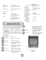
1-2. SPECIFICATIONS
Specifications for the model LBO-516 oscilloscope are given in
Table 1-1.
Table 1-1
SPECIFICATIONS
Vertical Amplifiers (Ch. 1 & 2)
Bandwidth (-3 dB)
DC coupled DC - 100 MHz
AC coupled 10 Hz - 100 MHz
Rise Time 3.5
K
S
Deflection Coefficients
Accuracy 5 mV/div to 5 V/div in 10 calibrated
steps, 1-2-5 sequence. Continuously
variable between steps. XI0
magnification adds 0.5, 1, and 2
mV/div steps for frequencies below 5
MHz
Input Impedance -+3%; -+5% with Xl0magniflca-tion
1 -2%, 25 pF +-3 pF
Maximum Input Voltage 400 V (DC plus AC peak)
1