WARNING!
THE SERVICING INSTRUCTIONS CONTAINED IN THIS MANUAL ARE FOR
USE BY QUALIFIED PERSONNEL ONLY. TO AVOID ELECTRIC SHOCK, DO
NOT PERFORM ANY SERVICING OTHER THAN THAT CONTAINED IN THE
OPERATING INSTRUCTIONS UNLESS YOU ARE QUALIFIED TO DO SO.
Страница 1: ......
Страница 2: ...INSTRUCTIONS CONTAINED IN THIS MANUAL ARE FOR USE BY QUALIFIED PERSONNEL ONLY TO AVOID ELECTRIC SHOCK DO NOT PERFORM ANY SERVICING OTHER THAN THAT CONTAINED IN THE OPERATING INSTRUCTIONS UNLESS YOU A...
Страница 3: ...3 1 Signal Connections 9 2 3 2 Single trace Operation 11 2 3 3 Triggering Alternatives 11 2 3 4 Probe Compensation 14 2 3 5 Dual trace Operation 15 2 3 6 Additive and Differential Operation 16 2 3 7...
Страница 4: ...timebases to simultaneously sweep the CRT effectively doubles this four trace display to an eight trace display The comprehensive triggering facilities of the LBO 516 include several features that eas...
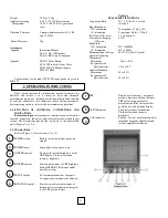
Страница 5: ...0 divisions Delayed TB Jitter 1 20 000 Trigger Circuits Sources CH l CH 2 Alternate Line External Modes Auto Normal Single shot Coupling AC DC HF reject TV vertical TV horizontal Slope or Holdoff Norm...
Страница 6: ...Lamp lights when power is on A INTEN control To adjust the overall brightness of the CRT display Clockwise rotation increases brightness B INTEN control Provides adjustment of CRT brightness during IN...
Страница 7: ...l For vertically positioning trace 1 on the POSITION control CRT screen Clockwise rotation moves the trace up Inoperative during X Y operation Channel 2 Vertical or For vertically positioning trace 2...
Страница 8: ...facilitates precise positioning when Xl0 magnification is used HORIZ DISPLAY To select the sweep mode Switches A push button sweeps the CRT at the main A timebase rate when pressed INTEN BY B push bu...
Страница 9: ...ering This trigger mode will also pass and differentiate waveforms in the 2 500 kHz range When triggered B sweep is selected as the horizontal display mode and the COUPLING switch is set to any positi...
Страница 10: ...the oscil loscope s primary wiring Cord Caddy Provides a quick method of securing the power cord and supports the oscilloscope for vertical operation Feet Supports the oscilloscope for shelf mounting...
Страница 11: ...nt of the instrument tilted upward for straight on viewing Press in the two Handle position Locks and simultaneously rotate the Handle so it points below the case then release the locks If the instrum...
Страница 12: ...ire lead coaxial cable and scope probes A simple lead wire may be sufficient when the signal level is high and the source impedance low such as TTL circuitry but is not often used Unshielded wire pick...
Страница 13: ...10...
Страница 14: ...DC AC peak 4 Set the A TIME DIV switch 24 so the desired number of cycles of signal are displayed For some measurements just 2 or 3 cycles are best for other measurements 50 100 cycles appears like a...
Страница 15: ...C voltages The line frequency trigger will sync signal at any reasonable multiple of the power line frequency The 0 2 V DIV and 2 V DIV positions both select external trigger signal applied to the EXT...
Страница 16: ...SLOPE switch 39 and the HOLDOFF control 42 The SLOPE switch determines whether the sweep will begin on a positive going or negative going slope of the trigger signal see Figure 2 8 In some cases the c...
Страница 17: ...ime between the end of one sweep and the start of the next in response to a trigger pulse This prevents the triggering of subsequent sweeps by the wrong trigger pulse in a complex waveform During norm...
Страница 18: ...O 516 since full amplification and attenuation facilities are provided for the two channels As was the case with Single trace Operation you have a choice here too not of channel selection but of how t...
Страница 19: ...iv becomes 2 KS div 0 1PS div becomes 01 PS div etc The 2 KS div sweep speed achievable by magnification is fast enough to display a single cycle of a 50 MHz signal across the CRT face 10 If the signa...
Страница 20: ...e CH 2 trace on the center graticule line 4 Use the PULL TRIPLE control 22 to set the third trace near the 10 dotted graticule line 5 Connect the signal to be observed to the CH 1 and CH 2 IN connecto...
Страница 21: ...0 so 02PS div becomes 2 KS div 8 The CH 2 INV switch 19 can be pushed in to display the difference signal between the CH 1 and CH 2 input signals instead of their sum 9 If your primary reason for sele...
Страница 22: ...ayed Sweep 4 Press the ALT HORIZ DISPLAY pushbutton 31 The B timebase trace s will now be displayed below its corres ponding A timebase trace s 5 If necessary adjust the A B TRACE SEP control 33 so th...
Страница 23: ...ended for single shot observation of fast transients 3 Press the NORM SWEEP MODE pushbutton 37 set the COUPLING switch 36 to DC and the SOURCE switch 34 to CH 1 4 Adjust the LEVEL control 40 for a sta...
Страница 24: ...e peak to peak voltage proceed as follows 1 Set up the LBO 516 for the vertical mode desired per the instructions in 2 3 BASIC OPERATING PROCEDURES 2 Adjust the TIME DIV switch 24 or 25 for two or thr...
Страница 25: ...number of divisions from that point to the ground reference line multiplied by the VOLTS DIV setting In the example used for Figure 2 15 the voltage for a 0 5 V div scale is 2 5 V 5 0 div X 0 5 V 7 If...
Страница 26: ...onds in this example Pulse width is the distance between points A and B In our example it is conveniently 1 5 divisions so the pulse width is 15 milliseconds However 1 5 divisions is a rather small di...
Страница 27: ...ulse width period etc or dual trace measurements lead and lag time The technique after the trace or traces are set up according to the desired procedure is as follows 1 Set the B TIME DIV switch 25 to...
Страница 28: ...rrectly compensated probes or equal lengths of the same type of coaxial cable to ensure equal delay times 2 Position the trigger SOURCE selector 34 to the channel with the cleanest and most stable tra...
Страница 29: ...DIV control 10 for the largest possible on screen display 6 Precisely center the trace horizontally with the horizontal POSITION control 29 or X FINE control 30 7 Count the number of divisions subten...
Страница 30: ...rom its dial The accuracy of this technique depends on the signal generator s calibration accuracy NOTE While many other ratios are theoretically possible drift in either signal frequency makes more c...
Страница 31: ...roduce the desired DUT output level 3 Set the CH 1 VOLTS DIV control 10 to the highest setting that produces over 7 divisions trace height 4 Use the CH 1 VARIABLE VOLTS DIV control 11 and CH 1 vertica...