background image

6

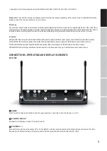
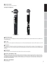
VOL

Rotary knob to adjust the output volume.

IR INTERFACE

Infra-red interface for synchronising the receiver’s radio channel with the transmitter.

ASC

Tosynchronisethetransmitterwiththeradiochannelsetinthereceiver,positiontheinfra-redportofthetransmitterdirectlyinlinewiththe

infra-redinterfaceofthereceiverandswitchonthetransmitterandreceiver(distanceabout10cm,IRinterfaceofthehandtransmitteris

belowthestatusLED,IRinterfaceofthepockettransmitteronthefrontside).NowpresstheASCbuttontostartthesynchronisationprocess.A

redLED indicator will light up in thewindow ofthe IR interfaceduringthe process.Aftera few seconds,the process is completedandoneof the

LED indicators ANTENNA A and B will light up (= wireless connection exists).

LEVEL INDICATOR

5-segment LED chain to display the audio signal level.

ANTENNA A - B

Indicator LEDs for the antenna systems A and B. The antenna system with the stronger radio signal is activated and the corresponding

indicator LED lights up.

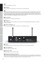
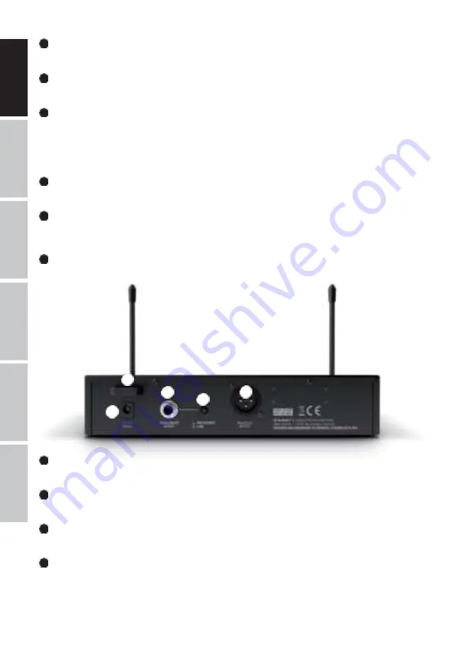
RECEPTION ANTENNAS A - B

For optimum reception, please position the antennas in an upward-facing V-position.

Low-voltage socket for the power supply to the device. Please use only the supplied mains adapter.

11

CABLE STRAIN-RELIEF

Cable strain relief for power adapter cable.

12

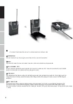
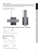
UNBALANCED OUTPUT

Unbalanced audio output via 6.3mm jack socket.

13

INSTRUMENT/LINE (UNBALANCED OUTPUT)

Switchforlevelandimpedance-matchingtoinstrumentsorlineinputsofanamplifierormixer.Usingasuitabletool (e.g.aballpointpen),

push the switch into the depressed INSTRUMENT position for connection to the input of an instrument amplifier (guitar or bass amp) and for

connection to the line-input of a mixer or amplifier, select the non-depressed position LINE.

4

5

6

7

8

9

11

12

14

13

10

10

DC SOCKET

Содержание LDU300

Страница 1: ...USER S MANUAL BEDIENUNGSANLEITUNG MANUEL D UTILISATION MANUAL DE USUARIO INSTRUKCJA OBS UGI MANUALE D USO Includes Wireless microphone system Adam Hall GmbH Model LDU300 LDU500...

Страница 2: ...SURES INTRODUCTION CONNECTIONS OPERATING AND DISPLAY ELEMENTS PIN ALLOCATION FOR MINI XLR CONNECTOR POCKET TRANSMITTER TROUBLESHOOTING OPTIONAL ACCESSORIES TECHNICAL DATA MANUFACTURER S DECLARATIONS 3...

Страница 3: ...e Thisequipmentmayonlyberepairedby authorized qualifiedpersonnel 20 Clean the equipment using a dry cloth 21 Complywithallapplicabledisposallawsinyourcountry Duringdisposalofpackaging pleaseseparatepl...

Страница 4: ...its are designed to provide reasonable protection against harmful interference in a residential installation This equipment generates usesandcanradiateradiofrequencyenergy and ifnotinstalledandusedina...

Страница 5: ...r plus hand held transmitter with dynamic capsule cardioid power supply 2 xAA batteries audio cable manual LDU30xBPH Receiverpluspockettransmitterandheadset black powersupply 2xAAbatteries audiocable...

Страница 6: ...ay the audio signal level ANTENNA A B Indicator LEDs for the antenna systemsA and B The antenna system with the stronger radio signal is activated and the corresponding indicator LED lights up RECEPTI...

Страница 7: ...he chargestatusisweak Inthiscase replacethebatteries 2xAA LR6type alkaline Duringthesynchronisationprocess theLEDflashesgreen and amber 18 IR INTERFACE Infra red interface for synchronising the radio...

Страница 8: ...l is muted 25 STATUS LED Ifthechargestatusofthebatteries issufficient theLEDlightsupgreenwhenthepockettransmitterisswitchedon IftheLEDlightsupred the chargestatusisweak Inthiscase replacethebatteries...

Страница 9: ...atterycompartmentcoveronthehousingandclickitintoplace Ifthetransmitteris notusedforalong period remove the batteries to avoid damage to the transmitter from leaking batteries ATTACHING THE POCKET TRAN...

Страница 10: ...er radio systems Distorted sound Transmitter Status LED is lit up red Receiver Peak LED on the receiver is lit Replace the batteries in the transmitter Reduce the signal level or reduce the input sens...

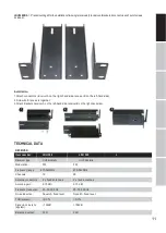
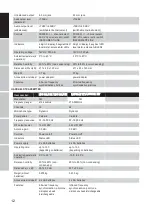
Страница 11: ...the left hand side receiver B on the right hand side TECHNICAL DATA RECEIVER Modulation FM FM Frequency range 470 542MHz 470 542MHz Channels 12 24 Antenna connectors 2 x fixed antennas 2 x fixed anten...

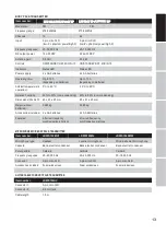
Страница 12: ...ot tone infra red frequency synchronisation pilot tone HAND HELD TRANSMITTER Frequency range 470 542MHz Channels 12 24 Microphone type Dynamic Dynamic Polar pattern Cardioid Cardioid Frequency respons...

Страница 13: ...1 x 25 mm 65 x 91 x 25 mm Weight without batteries 0 085 kg 0 085 kg Accessories included 2 x AA batteries 2 x AA batteries Features infra red frequency synchronisation pilot tone infra red frequency...

Страница 14: ...d users should contact either the retailer where they purchased thisproduct ortheirlocalgovernmentoffice fordetailsonwhereandhowtheycanrecyclethisiteminanenvironmentallyfriendlymanner Business users s...

Страница 15: ...Adam Hall GmbH Adam Hall Str 1 61267 Neu Anspach Germany Phone 49 6081 9419 0 adamhall com LD SYSTEMS COM REV 04...

Страница 16: ...to correct the interference by one or more of the following measures Reorient or relocate the receiving antenna Increase the separation between the equipment and receiver Connect the equipment into an...

Отзывы: